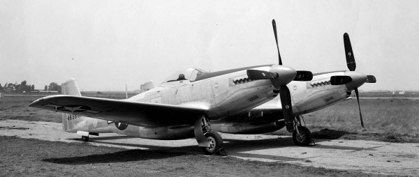
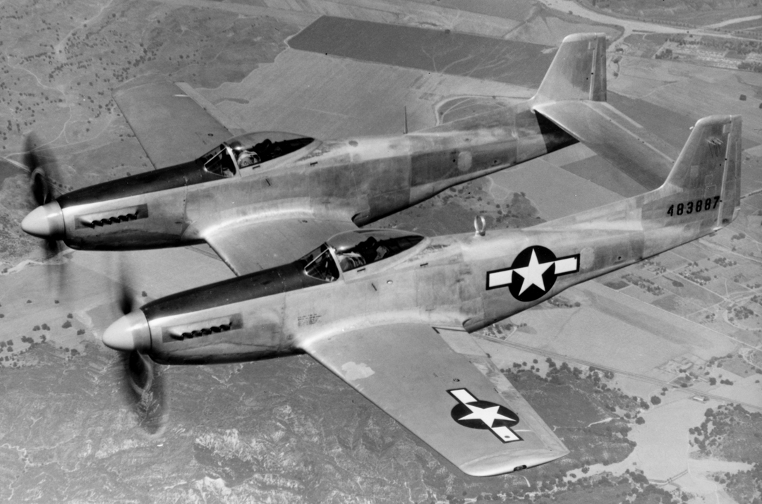
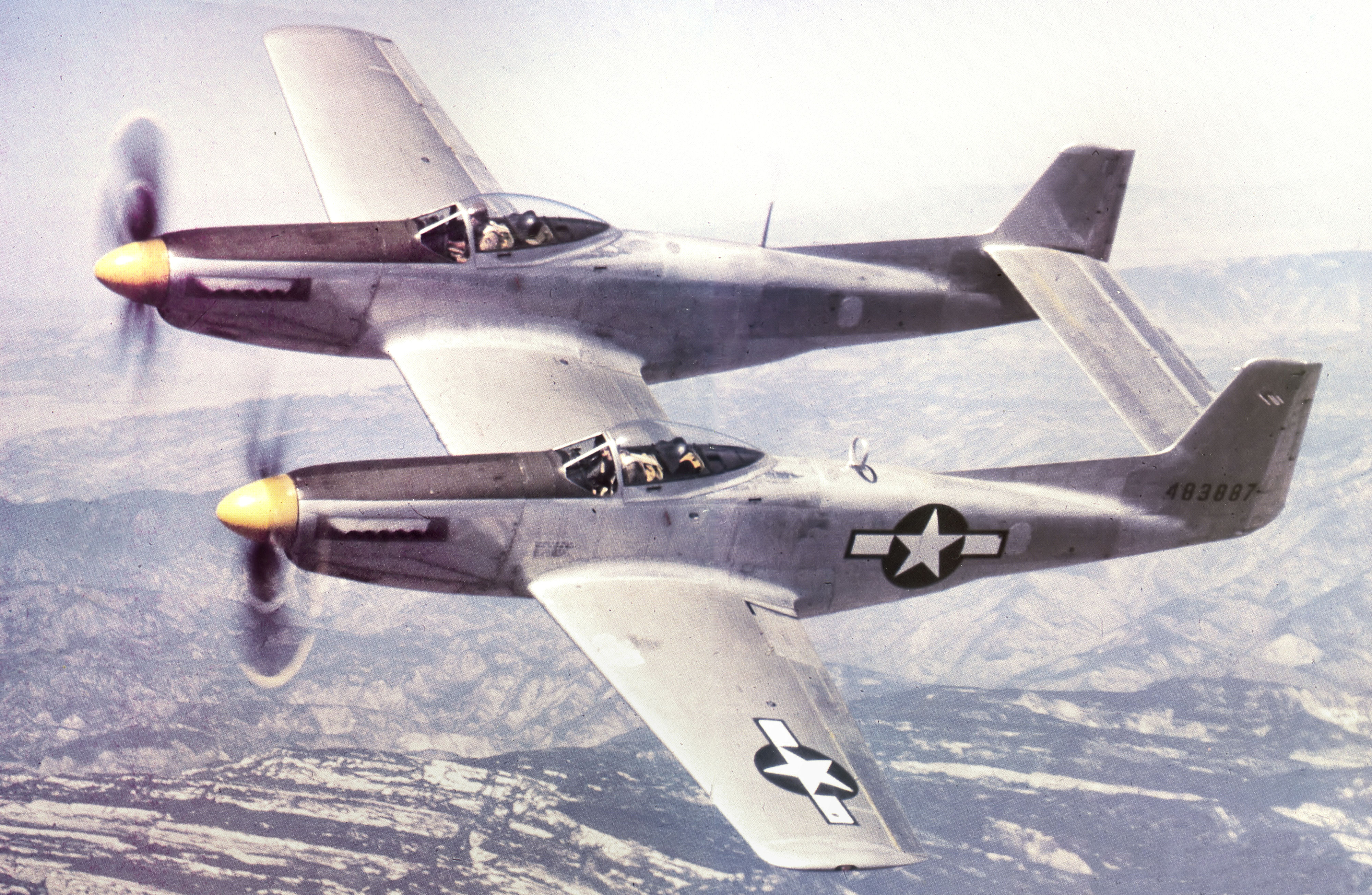
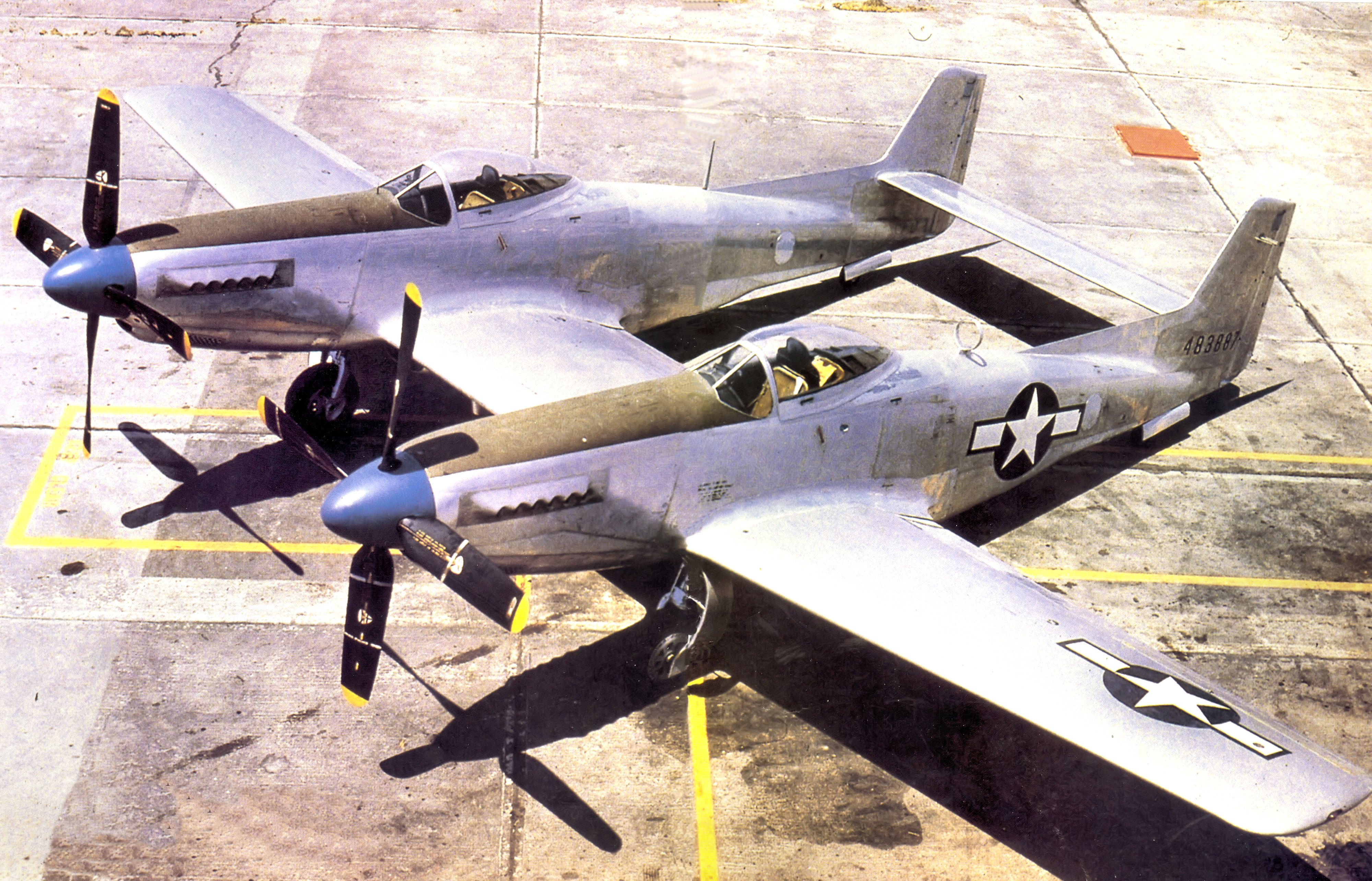
![XP-82 in flight]()
While we hadn’t expected to have a progress report on the XP-82 until June, WarbirdsNews is thrilled to have received the latest Twin Mustang restoration update from Tom Reilly at his workshop in Douglas, Georgia (Check out the XP-82 website HERE). We’ve actually got kind of a bumper report here for you all, including details from both February and April which we will share sequentially….. Enjoy!
February’s Report
![Right hand wing showing the control surfaces in final assembly. (photo via Tom Reilly)]()
Right hand wing showing the control surfaces in final assembly. (photo via Tom Reilly)
Wings
The preliminary fitting and set-up of the ailerons, aileron and flap hinges has now been completed on the right-hand wing. It has been an extremely difficult and time consuming job converting the Alaskan “H” model boosted ailerons back to the non-boosted XP-82 systems. The “E” thru “H” model ailerons are basically the same as the XP’s, but all of the hinges and mechanisms that operate the ailerons are completely different. There was a lot of “brain burn” and many engineering hours that a number of team members had to exhaust to make this boosted-to-non-boosted system work. Reilly reckons it was one of the most difficult jobs on the entire XP-82 restoration. The systems are completed and work perfectly, which gave the the XP-82 crew a real feeling of accomplishment.
![Dorsal fin approaching final assembly. (photo via Tom Reilly)]()
Dorsal fin approaching final assembly. (photo via Tom Reilly)
Tail Section/Dorsals
The final fitting and riveting of the two dorsal fins is now completed. Both formed, welded and removable access dorsal fairings are also completed and undergoing final fitting.
![Center gun bay door. (photo via Tom Reilly)]()
Center gun bay door. (photo via Tom Reilly)
Center Section Gun and Ammo Bay Doors
The right-hand ammo bay door is now completely finished and fitted. The left-hand ammo bay door is awaiting only one leading edge extrusion to be riveted in place for completion. The large central gun bay door is awaiting cad plating of the two latch mechanisms. Reilly’s team had to manufacture one complete latch mechanism assembly in-house as they were only able to recover one salvageable assembly from the Alaska impact site. When this plating is finished, the latches will be installed and then the upper and lower skin riveting can be completed. All about a one day job.
![Right hand ammo bay door (near) and the left hand unit to the rear. (photo via Tom Reilly)]()
Right hand ammo bay door (near) and the left hand unit to the rear. (photo via Tom Reilly)
![Gun bay door latch mechanism. (photo via Tom Reilly)]()
Gun bay door latch mechanism. (photo via Tom Reilly)
Fuel Systems
All six fuel pumps (four in-tank submerged boost pumps and two engine driven pumps) have been overhauled and shipped back to Douglas.
![The four submerged boost pumps (top) and two engine driven boost pumps (bottom). (photo via Tom Reilly)]()
The four submerged boost pumps (top) and two engine driven boost pumps (bottom). (photo via Tom Reilly)
The Twin Mustang Team was able to purchase four new fuel necks, New Old Stock from a surplus dealer, however they did require being shortened vertically and re-welded to fit the XP-82 hat channel vertical measurements. They are now at the cad plating facility, but should be back within a week.
![New Old Stock fuel necks. (photo via Tom Reilly)]()
New Old Stock fuel necks. (photo via Tom Reilly)
The team has the three cardboard fuel tank patterns completed and these will be shipped to the fuel tank manufacturing company in Eagle River, Wisconsin to use in the remanufacture brand new tanks. The team thankfully only had to make three of the six tanks, as the tank company can mirror image the patterns for the opposing side. These tank patterns took a lot more time than planned, because the team had to duplicate exactly the complex shapes inside the wings and center section. The team is now into laying out all of the fuel feed, vent and drop tank(s) pressure/fuel lines. North American ran these lines inside each fuel tank bay, so the tanks had to be shaped to allow their passage.
![Cardboard fuel tank patterns. (photo via Tom Reilly)]()
Cardboard fuel tank patterns. (photo via Tom Reilly)
The team also had to manufacture the fuel scupper pots and drain lines to which the four fuel caps and mounts attach. A scupper is a pot that collects and dumps overboard any fuel spilled during fueling so that the wasted fuel does not enter the wing between the tank and the wing structure creating a fire hazard.
The two fuel check/flapper valves are almost complete, and awaiting the four bronze flappers being machined by one of the outside machine shops. These two check valve assemblies direct the fuel to each engine when either tank boost pump is running and do not allow the fuel to transfer to another fuel tank. The term for this is “cross feed” to the engine and not “cross flow” to another tank. Reilly was able to salvage these two complicated check valves from the Colorado parts, but had to have the four internal flapper valves remachined.
![Gear door uplock cylinders. (photo via Tom Reilly)]()
Gear door uplock cylinders. (photo via Tom Reilly)
Gear Door Up-Lock Cylinders
The new hydraulic piston/shaft has been assembled inside the new hydraulic cylinder barrel and is awaiting installation.
Engine/Propeller Test Runs
Tom Reilly talked with Mike Nixon recently. Nixon’s company, Vintage V-12s, overhauled the project’s two Merlin engines. Reilly discussed the logistics of whether to send the Twin Mustang’s two Merlin engines back to California for test-cell runs, or run them while mounted on the XP-82 aircraft itself. Nixon told Reilly that he would prefer to come to Georgia and run them in on the airframe. That way all of the systems, i.e., fuel, oil, coolant, propeller, etc., etc., would be checked out at once. This will save the project a substantial amount of money by not having to ship the engines back to California for the test run(s) and then in turn back to Georgia. The only thing necessary is to to ship the two empty engine cans (2,000 lbs. each) back to California. Reilly told Nixon to put them on Delta as carry-on luggage — he said he would try.
Windshields/Canopies
The team is just getting ready to start the final completion of the two windshield assemblies. Reilly decided to pull the team off the windshields to complete the dorsals, gun and ammo bay doors and fuel tank patterns for sub-contract timing reasons. Both canopies have now been completed on opening and closing, elevation, pitch and rotational alignment for a couple of months. These alignments had to completed first to allow the final alignment of all the windshield parts to fit each forward canopy bow.
![Rudder pedal assemblies. (photo via Tom Reilly)]()
Rudder pedal assemblies. (photo via Tom Reilly)
![Rudder pedal adjustment rods. (photo via Tom Reilly)]()
Rudder pedal adjustment rods. (photo via Tom Reilly)
Rudder Pedals, Mounting Arms and Elevator “T” Forging
Both right-hand cockpit rudder pedals, arms and adjustment rods are now completed and being installed. The elevator “T” forging that arrived back from the machine shop last month has had the new “DD 6” bearings pressed in and is also now being installed in the right-hand cockpit. With these pedals, arms, adjustment rods and elevator “T” forgings installed, all of the controls in both cockpits will now be completed.
![4562020150_b5e689a81c_z]()
![4562019692_91352a5f97_z]()
And now for the April Update…
It seems that we can work on some specific systems for months, and it never seems to get done. Well, this month quite a few of these endless jobs got completed.
![Tom Reilly working on the windscreens. (photo via Tom Reilly)]()
Tom Reilly working on the windscreens. (photo via Tom Reilly)
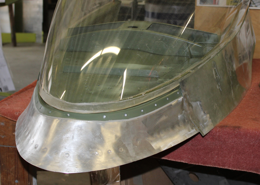
Windshields
Both are now completed with all their glass panels installed with PRC (epoxy) edge sealants and mounted on each fuselage. The last thing that needs to be completed is the special rubber seal inside the windshield bow that seals the canopy to the bow when the canopy is closed.
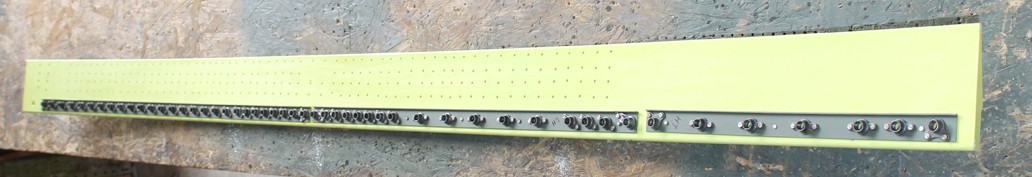
![The ailerons being fitted to an outer wing panel. (photo via Tom Reilly)]()
The ailerons being fitted to the right outer wing panel. (photo via Tom Reilly)
![Paul Randall working on the left hand aileron. (photo via Tom Reilly)]()
Paul Randall working on the left hand aileron. (photo via Tom Reilly)
![Aileron hinge fitting. (photo via Tom Reilly)]()
Aileron hinge fitting. (photo via Tom Reilly)
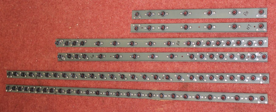
Ailerons
Both skinned ailerons and bell cranks on the right-hand wing are now complete and final-fitted on all of their hinges. Both ailerons (two per wing) and all the mechanisms operate as smooth as silk. The final fitting of the two main XP attach fittings in the left-hand ailerons is now complete. As mentioned over the past few months, the fitting of the remaining aileron hinges is progressing quite rapidly as the “reinvention of the wheel” was completed on the right-hand wing. Designing, manufacturing and final fitting the new non-boosted XP hinge points to the boosted “E” model ailerons was quite a brain-burn. Two of Reilly’s lead sheet metal crew took on the challenge and made the tasks look simple. He expects both left-hand ailerons to be completed mid May, and then the final skinning for the bottom of each wing will begin.
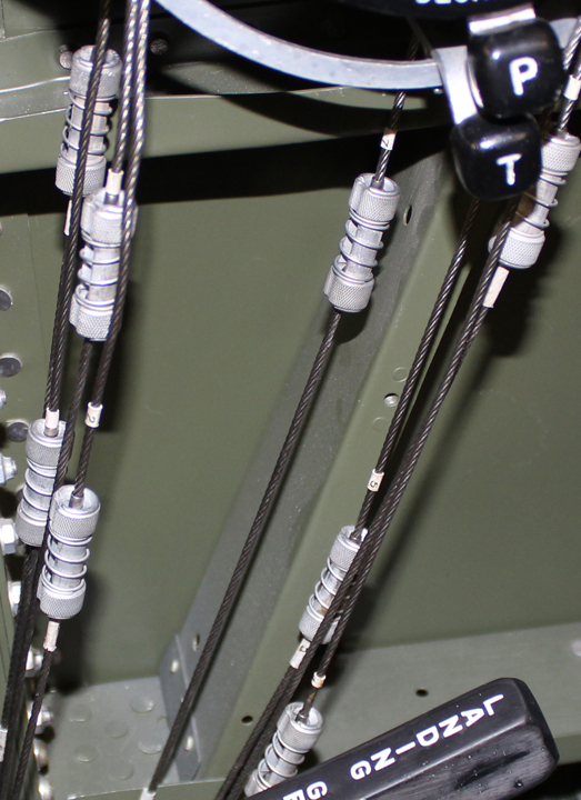
![Some of the complex tubing formed by a volunteer named Gerald. (photo via Tom Reilly)]()
Some of the complex tubing formed by a volunteer named Gerald. (photo via Tom Reilly)
Gear Door Retract/Door Up-Lock Hook Cylinders
Mounting of the overhauled cylinders with their coiled flex aluminum lines was a very difficult fit, not allowing anything to rub. Both are now completed.
Fuel Tank Feed & Vent Lines/Tubes
These tubes are projected to be complete by mid May. Two team members spent two weeks forming patterns out of malleable tubing that were sent out with the new tubing (multiple sizes of 5052-0) to be formed. These tubes must be formed (bent) with a special mandrel machine bender or they will kink. Reilly purchased a mandrel bender a year ago that hadn’t been assembled or used for years. This is a very large heavy manually operated bending machine that is 15’ long and weighs more than a thousand pounds. Tom Reilly loaned the machine and all of its forming dies to Gerald, a project volunteer, who lives in Mississippi. Gerald is a retired Naval officer, radar expert and a EC-121 (Connie), P2V Neptune and P-3 Orion crew and driver (pilot). He spent weeks repairing all of the parts of this machine (lots) and is now forming all of the fuel feed and vent aluminum tubing.
![Seats for the XP-82 project. (photo via Tom Reilly)]()
Seats for the XP-82 project. (photo via Tom Reilly)
Seats
Reilly’s team assembled the pilot and copilot fold-back seats. (Each seat can fold back and the rudder pedals disconnect to slide forward so either pilot could sleep on long missions.) These went together quite quickly as all of the parts were detailed and awaiting assembly these few months.
![Drawing of the tail wheel mechanism. (photo via Tom Reilly)]()
Drawing of the tail wheel mechanism. (photo via Tom Reilly)
![Tail wheel forks and assembled parts. (photo via Tom Reilly)]()
Tail wheel forks and assembled parts. (photo via Tom Reilly)
Tail Wheel Assemblies
Two team members have started on the two massively complicated tail wheel retract assemblies. There are literally hundreds of moving parts in these retractable and steerable units. Fortunately, Reilly now has almost all of the parts, and two machine shops are completing the last few missing items.
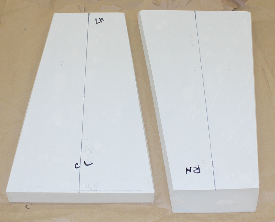
![Pressing the interior skins for the coolant exit doors (photo via Tom Reilly)]()
Pressing the interior skins for the coolant exit doors (photo via Tom Reilly)
![Coolant exit doors. (photo via Tom Reilly)]()
Coolant exit doors. (photo via Tom Reilly)
![Coolant exit doors. (photo via Tom Reilly)]()
Coolant exit doors. (photo via Tom Reilly)
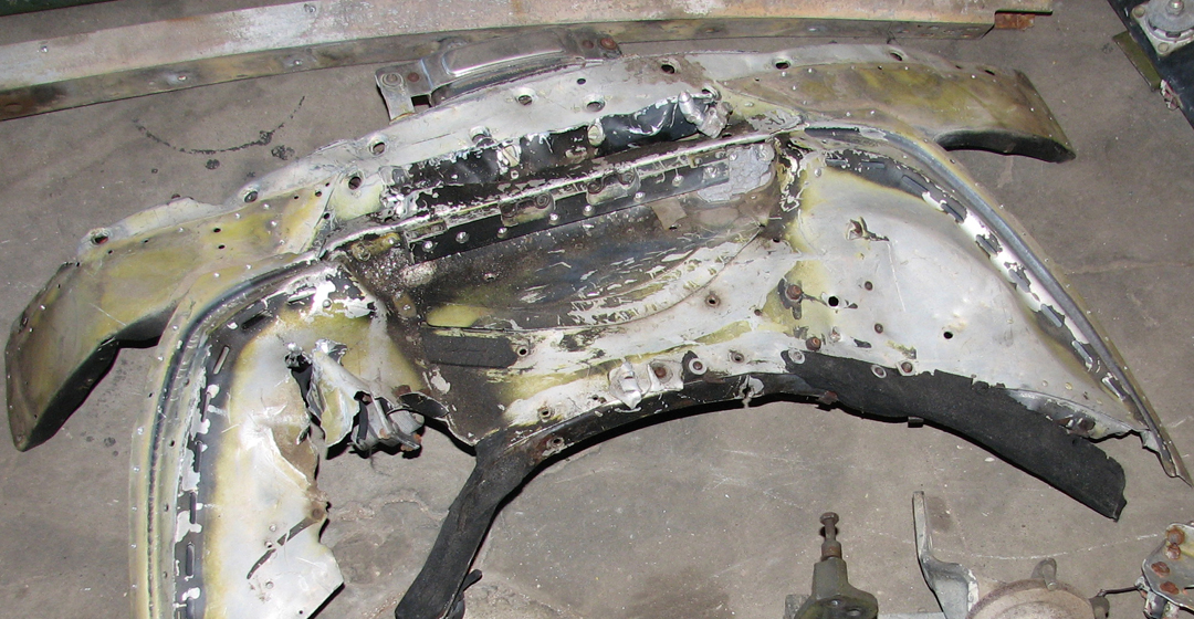
Coolant Exit Doors
Reilly got the two interior skins for the exit doors pressed. They were a very difficult pressing because each had a combination of concave and convex shapes, making them very challenging to form on an English wheel. Reilly’s team has now fitted them to the internal framework and exterior skins, and has test-fitted both to their respective fuselage coolant exit door tunnels. He expect both of these to be completed and mounted by this summer.
![(photo via Tom Reilly)]()
An Egg Model of the F-82!!! (photo via Tom Reilly)
And that’s all for the moment. Many thanks again to Tom Reilly for the update! You can learn more about the project on their blog HERE. Please be sure to check back with WarbirdsNews in early June when we hope to have the next episode following the XP-82′s road to recovery!