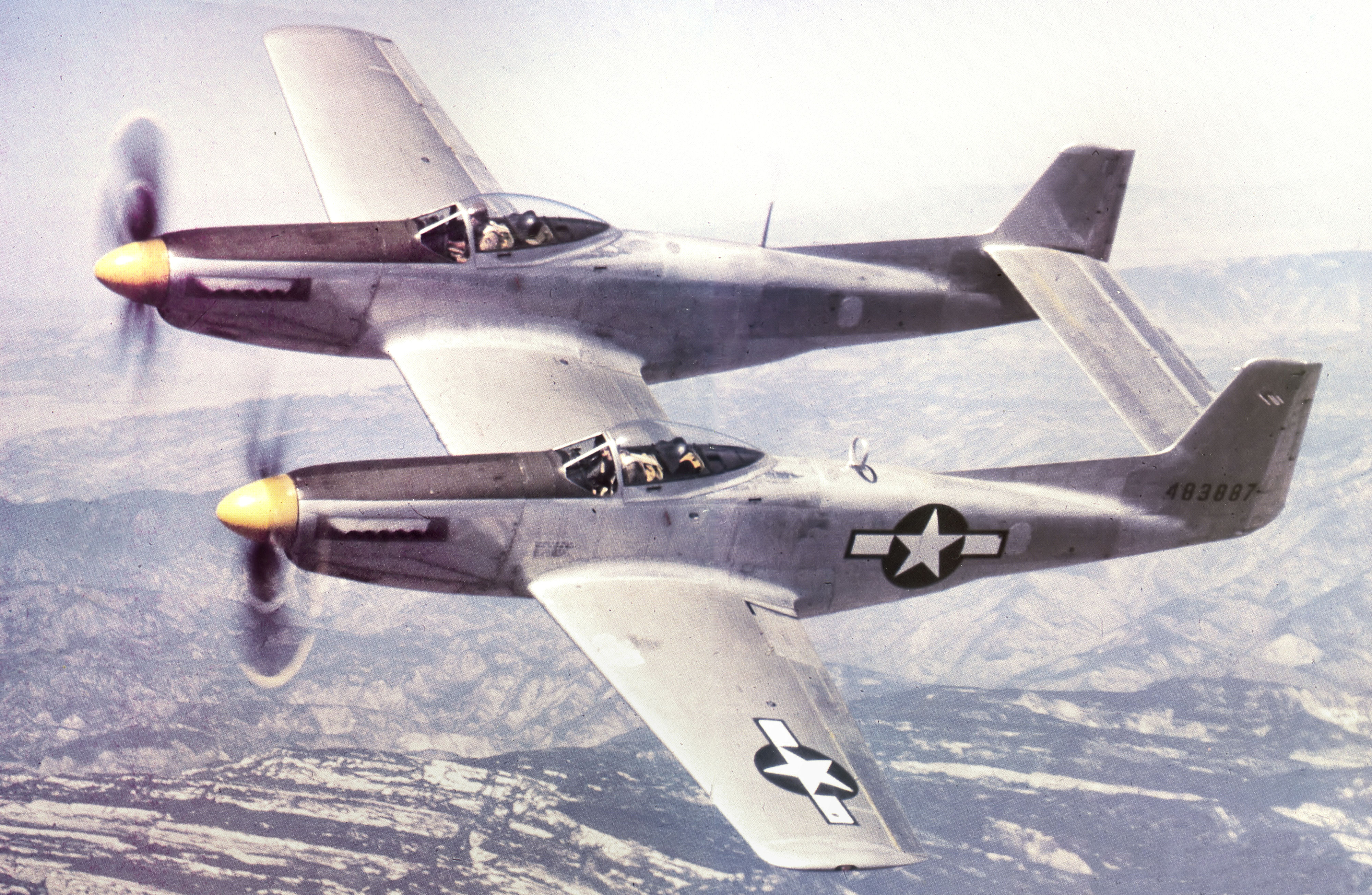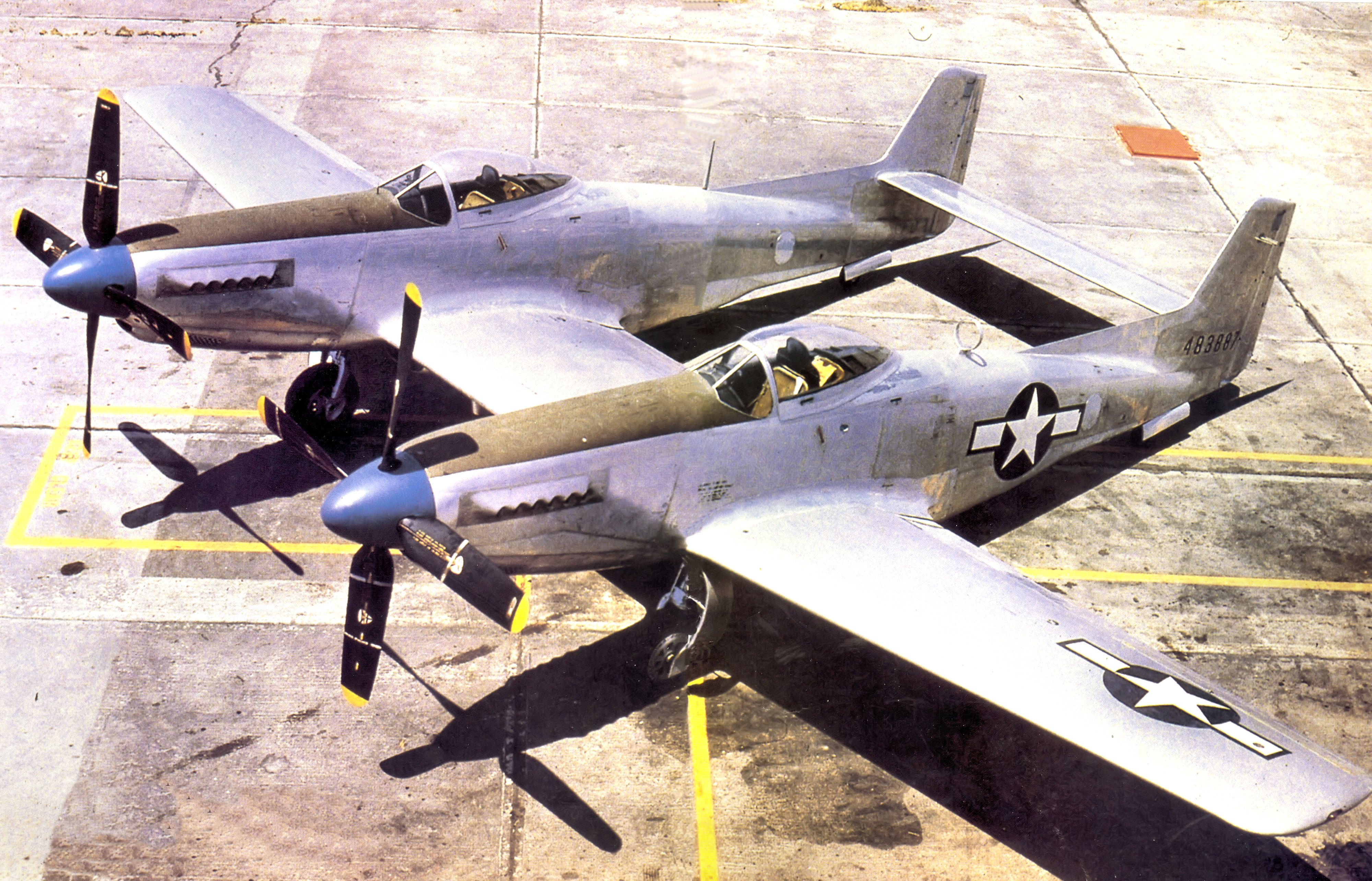
North American XP-82 Twin Mustang 44-83887 in 1945
WarbirdsNews has received the latest XP-82 Twin Mustang restoration update from Tom Reilly at his workshop in Douglas, Georgia. Here’s what they’ve been up to this month!
Firewall Forwards
Two of the team members have spent the entire month manufacturing replacement lower cowl ribs. These are the ribs that the lower cowling attaches with Dzus fasteners. The project had some of the original ribs to use as patterns, but they were totally non-usable due to damage caused by the aircraft being moved countless times when it was in the field in Ohio. All of the upper cowl ribs were completed last month, and when the lower ones are completed this month they will all go together for heat treat up to T4 condition (hardened).

Two of the sixteen lower cowling ribs. (photo via Tom Reilly)

Another pair of the sixteen total lower cowling ribs. (photo via Tom Reilly)
Electrical
All of the generator and starter firewall forward electrical harnesses have now been fit, cut to length, and their large amperage terminals crimped and soldered on. Reilly’s team is in the process of completing the low amperage firewall forward Cannon plug harnesses that go forward and attach to all of the miscellaneous electrical components: tachometer, starter and preoil relays, generator field, supercharger solenoid, mixture and carburetor air temperature controls, oil, glycol and carburetor air temp probes, propeller feather and chip detectors. Both feather pumps for the MT Propellers are now permanently installed on the left-hand lower firewall armor plate.

MT Propeller feather pump mounted on firewall. (photo via Tom Reilly)

Start and pre-oil relays. (photo via Tom Reilly)
Carburetor Air Temperature (CAT) Control Motors
These two CAT motors have been an ongoing headache. For years, Reilly has tried to find replacements, because the originals were open to the weather and full of water for fifty plus years. Both motors, all the sequential limiting switches, and all the wiring and gearing were nothing but a pile of rust and corrosion. Reilly offered this task to one of his ‘wizard volunteers’, Gerald. He took this task on to find replacement limit switches (the original style is no longer available), get the motor armatures and fields rewound, and remanufacture all the interior motor and switch mounting brackets.

The XP-82 Carburetor Air Temperature (CAT) Control Motor. The unit had suffered extensive corrosion damage internally due to decades of exposure to the elements. (photo via Tom Reilly)

The heavily corroded interior of the XP-82 CAT limit switch and gear housing. (photo via Tom Reilly)
Gerald found an electric motor rewind shop that rewound the tiny motors and fields, and repaired the brake assemblies which instantaneously stop the motors at the proper selected positions. There are four positions for this carburetor air control system: ram air, half-hot air, full-hot air, and filtered air. The carburetor air-induction trunks of an aircraft engine must have the ability to control the temperature of the air being forced into the carburetor due to different environmental conditions (temperature and moisture) during flight. The pilot controls this temperature by rotating a switch on the instrument panel to stop the control in each desired position.
All of the limit switch and Cannon plug wiring has now been completed.

The specialty, miniature 16 tooth gears which Weezie managed to find at a New York supplier which proved invaluable to the overhaul of the CAT units. The truck key is included to show just how tiny these gears are! (photo via Tom Reilly)

The magnificently overhauled limit switch housing. Compare this to the corroded mess shown in a previous image. (photo via Tom Reilly)
Oil/Fuel Pressure Senders, Oil & Coolant Lines
All four units are now permanently attached, Aeroquip-hosed from the engine to the sender, and sender to the firewall. These four NOS Rochester units were contributed to the project by Larry Kelley (owner of the B-25J known as ‘Panchito’). Reilly was really grateful to Larry Kelley for this help, and urges everyone to read the article about ‘Panchito’ in the December issue of AOPA Pilot magazine.
The planned trip to mandrel-bend all of the firewall forward oil and coolant lines scheduled for last month had to be postponed, but Reilly hopes to complete this task by the end of December.

Two of the four New Old Stock oil/fuel pressure sender units which Larry Kelley supplied to the XP-82 project, complete with original documentation! (photo via Tom Reilly)

The Right Hand pressure sender unit installation. (photo via Tom Reilly)
Belly Scoops
The final fitting and riveting of the fairing panels are complete on the left scoop, along with both forward airfoil attach rails. This fitting has been a complex process to rivet all of the required threaded nut plates for attaching the fairing panels to the lower side of the center section. These nut plates had to be installed between and under the hat channels in the 95-gallon center section fuel tank bays, and a number of them had to be installed in the hydraulic bay compartment in amongst all of the hydraulic lines and components. A fun job, but now finally completed.

One of the massive belly scoops for the XP-82 project. (photo via Tom Reilly)

The airfoil support rods for mounting the forward part of each belly scoop (shown with a pen for scale). (photo via Tom Reilly)
Seats/Armor Plate/Weight & Balance, Center of Gravity (C/G)
The final assembly of all the seat elevation parts is now complete. Reilly decided to replaced the original steel armor plates with remanufactured units with identical dimensions using 1/4” aluminum plate instead of the original steel to save weight. Reilly had originally planned to hold this decision until the point of doing the aircraft ‘weight and balance’ to see where he needed to add or subtract weight. However, the original steel armor plates were positioned so close to the neutral C/G point that it would not make any substantial difference in the center of gravity of the aircraft if they were made of aluminum.

One of the fully assembled pilot’s seats. (photo via Tom Reilly)
(When manufacturing and/or restoring any aircraft, one has to be very careful when it comes to the weight and balance of the finished aircraft. All aircraft must maintain a specific balance range of inches so that the aircraft flies properly. The ‘weight and balance’ is determined by weighing the aircraft after it is completed to determine where the center of gravity is. The center of gravity can be corrected by adding or taking away factory lead balance weights positioned in the tail.)

The armor plate, replicated in aluminum, rather than original steel to save weight. The welded brackets are for attaching to the seat rail brackets. (photo via Tom Reilly)
And that’s all for November, 2015!
Many thanks again to Tom Reilly for the update! You can learn more about the project on their blog HERE. Please be sure to check back with WarbirdsNews in January, 2016 for the next installment in the story following the XP-82′s road to recovery!