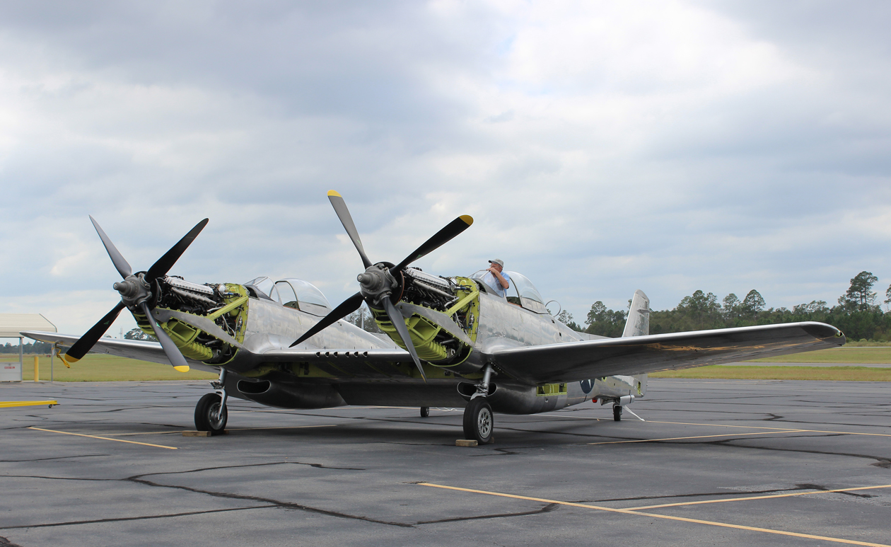
Following the momentous news over last weekend concerning the XP-82 Twin Mustang’s first engine runs in Douglas, Georgia, we wanted to know a few more details. A lot of major developments have been occurring with this incredible project in recent weeks, what with the move to a new, much larger hangar, attaching the outer wing panels for the first time, and of course the engine runs. We contacted Tom Reilly to learn more about what his restoration team has been up to, and thought our readers would be as eager as we were to see his responses… so here they are!
Photo by Louisa Barendse
WN: When did you move the XP-82 from the project hangar, and did you move the shop as well? TR: The XP was moved to the other hangar on 12 October. We are now located on the other side of the airport in the most southern hangar. A partial shop was moved, only what we need to compete the restoration.
WN: How did the outer wing panel installation go? TR: The wing installation went smoothly and only took minutes. They went on with no issues, and are temporarily installed at this time.
WN: Who conducted the engine tests? TR: The General Manager of Vintage V12s [Ed. Jose’ Flores] was here and did the starts.
WN: How did the engine runs go, and did you test any other systems? TR: The runs went great on the first starts. Other than temps and pressures, no other systems were brought online.
WN: Was there a reason for conducting the first engine runs inside the hangar? TR: It was raining. The fire department was onsite.
WN: The video shows just one engine being run, did you test both engines? TR: Yes
WN: What restoration items are still remaining? TR: Main and tail gear doors, top cowls, coolant door motor wiring and retractions.
WN: Do you have any tentative dates for a first flight, or pilots in mind to conduct it? TR: No date for the first flight yet. We have talked to warbird test pilots Ray Fowler and Eliot Cross.
WN: How would you sum up the project so far? TR: … It has been 8 years and one of the most enjoyable restorations that I have worked on ever!
WarbirdsNews wishes to thank Tom Reilly and Louisa Barendse for spending time with us and sharing some of the recent details of the work going on with this exciting project. We hope to provide news of addition progress very soon. To visit the restoration’s blog, please click HERE.
The XP-82 sitting out in the sunshine during her move to the new hangar. (photo via Tom Reilly)
WarbirdsNews has received the latest XP-82 Twin Mustang restoration update from Tom Reilly at his workshop in Douglas, Georgia. Here’s what they’ve been up to this past month!
First of all, the project is fully moved into their new hangar. A lot of progress has been taking place with the finishing touches on the aircraft too!
Firewall Forwards
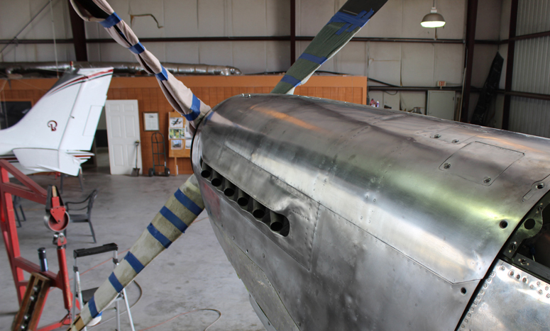
The last left-hand engine upper, lower and side cowling items are now complete. The final installation of the left-hand propeller has also been completed, with the exception of the spinner. The spinner will remain off during the engine test runs to allow easier observation of any potential leaks.
(photo via Tom Reilly)(photo via Tom Reilly)
According to Tom Reilly, the final mounting of the right-hand propeller should be complete by the time these words are read.
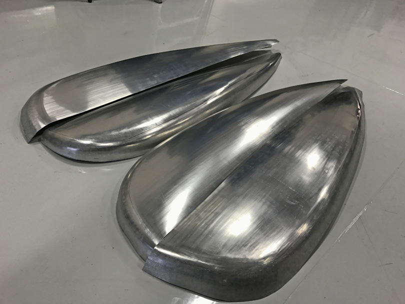
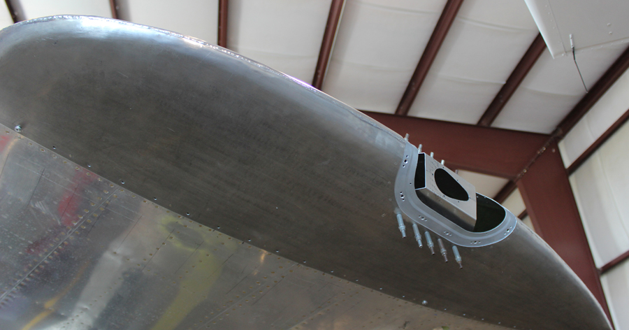
The induction-trunk lower intake for the left-hand engine. (photo via Tom Reilly)
The induction-trunk lower intakes for the right-hand and left-hand engines have now been completed and are being final-fitted, awaiting sanding and polishing. These were very difficult forming tasks. The rotating carb air temperature barrel mechanisms and mounting structure are now also final-fitted, but presently removed to allow painting.
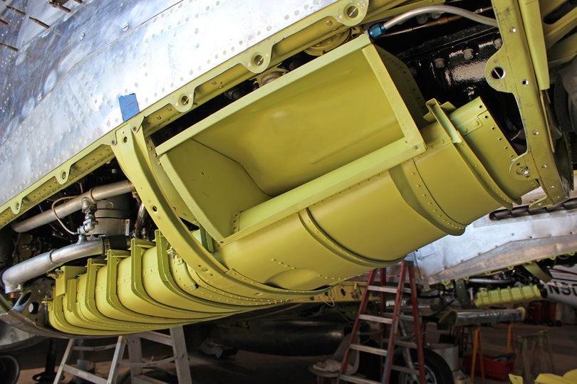
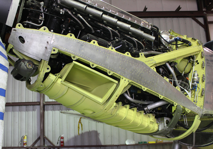
The heat exchangers now nestle properly into the oil tanks on each engine. You can see how the rings slot into the tank in this shot. (photo via Tom Reilly)
The mounting installation of both heat exchangers (oil/intercoolers) is now complete. These parts both presented a problem, as they interfered with the upper cowling arch framework. The project had the original exchanger mounting straps attached to the dishpans, but did not have the original rings that mounted the exchangers to the straps. When Reilly’s team machined the rings, as per the XP-82 drawings, the exchangers would mount about an inch higher and not nestle into the two factory-formed notches in the oil tanks. After redesigning and machining the four new mounting rings, the restoration team solved the interference problem.
Engines/Props
The test running of both engines and all of their associated systems will start this December.
Outboard Wings
The English wheel forming of the two wing tips is progressing rapidly. Both upper wing tip panels are finished and the two lowers are in production. Tom Reilly expects them to be completed sometime in mid-December.
The exquisitely re-manufactured upper wingtip skins. (photo via Tom Reilly)
Landing Gear/Doors
The subcontract machine work of the press dies for the inboard gear doors is progressing nicely. The outboard door skins have been ready for some time now, and are awaiting the completion of both interior frameworks.
Tail Wheel Steering
Both tail wheel steering mechanisms are now final-installed, less tensioning. A number of moving parts are required to turn the two tail wheels left and right.
Part of the tail wheel steering mechanism. (photo via Tom Reilly)
Brakes
The machine shop is currently 3-D modeling both brake calipers. These brake assemblies fit only the XP-82 and subsequent Twin Mustang production models. They have a unique, anti-skid design and worked extremely well according to pilot reports.
Authentic Interior Cockpit Furnishings
The restoration is heavily involved with completing the internal parts for each cockpit: gun sights, gun camera, oxygen regulators, gauges and blinkers, original radio heads, heater and defrost controls, exterior ADF ring antennae, etc., etc.
VIP Visitor
The project had the honor of a visit from WWII Army Air Force veteran Col. Robert Thacker, now 98 years young. He is famous for piloting the P-82B named “Betty Jo” on its non-stop flight from Hawaii to LaGuardia Airport in New York on February 27th, 1947. Tom Reilly was amazed by how sharp and alert Col.Thacker is for such an advanced age. He still remembered every detail that went into the record-breaking flight’s preparation – the test flights, the additional fuel tanks installed inside the fuselages, and the exterior drop tanks … as well as why three of the four drop tanks could not be jettisoned (the sway braces were over-tightened by a ground crewman which prevented the release hooks from operating). One of the tanks did drop leaving the other three under the wings, creating a dramatic yaw condition which required a substantial amount of rudder trim drag.
DAYTON, Ohio — Col. Bob Thacker stands beside the North American F-82B Twin Mustang in the Modern Flight Gallery at the National Museum of the United States Air Force. The museum’s F-82B, “Betty-Jo,” flew from Hawaii to New York on Feb. 27-28, 1947, a distance of 5,051 miles, the longest non-stop flight ever made by a propeller-driven fighter. (U.S. Air Force photo – via Tom Reilly)A vintage shot of ‘Betty Joe’. (photo via Tom Reilly)
Col. Thacker described, in detail, the additional 150-gallon fuel tanks installed behind each pilot seat and the 60-gallon tank installed in the gun bay. He even distinctly remembered a plug being inadvertently left in the gun bay tank vent line during one of the test flights, resulting in the tank collapsing and a replacement having to be manufactured.
The P-82 had a total of 1,860 gallons of fuel at lift off, including the 600 gallons of production center section and wing tanks, two 300 gallon and two 150 gallon wing drop tanks, and the 360 gallons of additional internal tanks added for the long flight.
Total distance from Hawaii to New York – 4,899 statute miles. 14.5 hours total flight time. Average cruise speed – 338 miles per hour. Taking tail winds into consideration, that’s 300+ mph cruise.
Tom Reilly hopes his own memory of the details Col.Thacker related during his visit three weeks ago is as good as his memory at 98 years young!
Concorde Battery
Tom Reilly also wished to offer special thanks to Mr. Don Grunke of Concorde Battery Corporation. Concorde contributed a brand new battery for the XP-82 project. The quality of their batteries is outstanding, according to Reilly, with one of their units lasting nine years in his B-25 Mitchell!
And that’s all of the news for November, 2016!
———————————-
Many thanks again to Tom Reilly for the update! You can learn more about the project on their blog HERE. Please be sure to check back with WarbirdsNews in January, 2017 for the next installment in the story following the XP-82′s road to recovery!
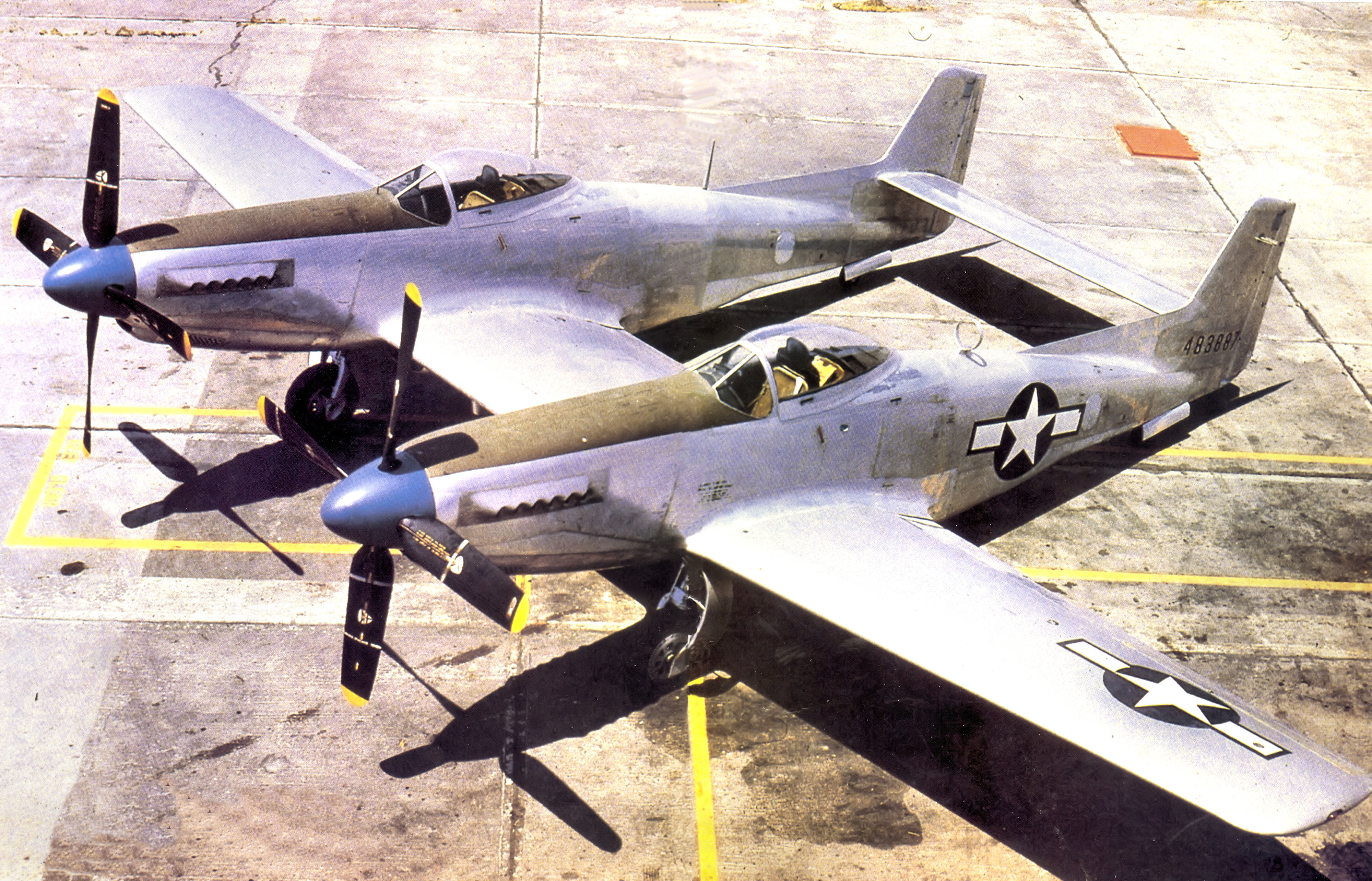
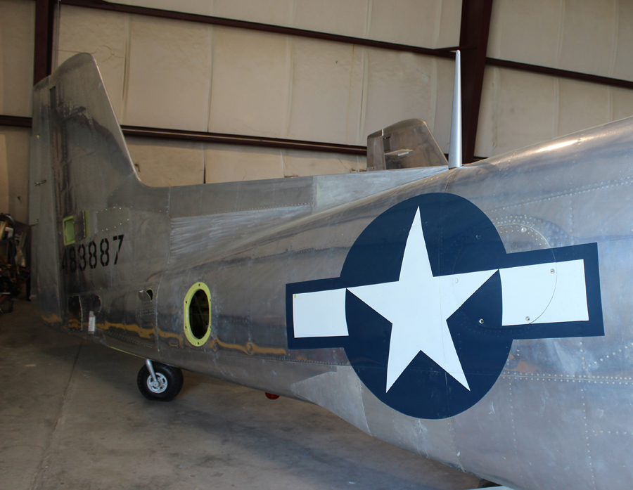
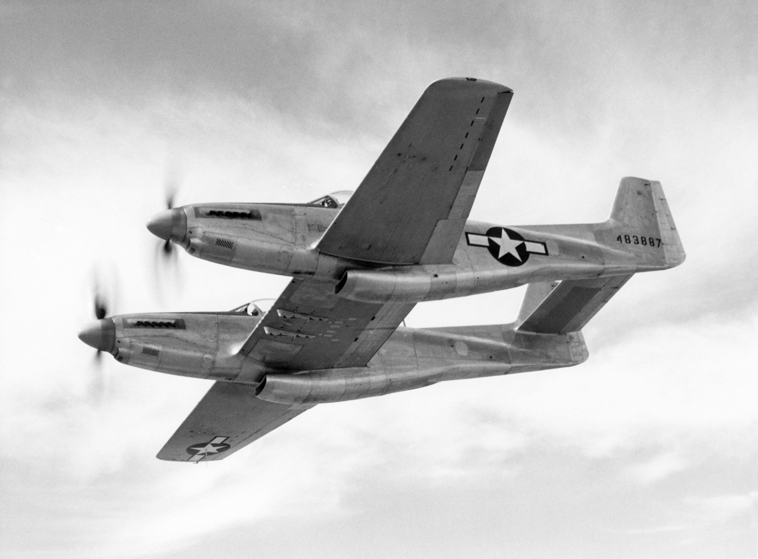
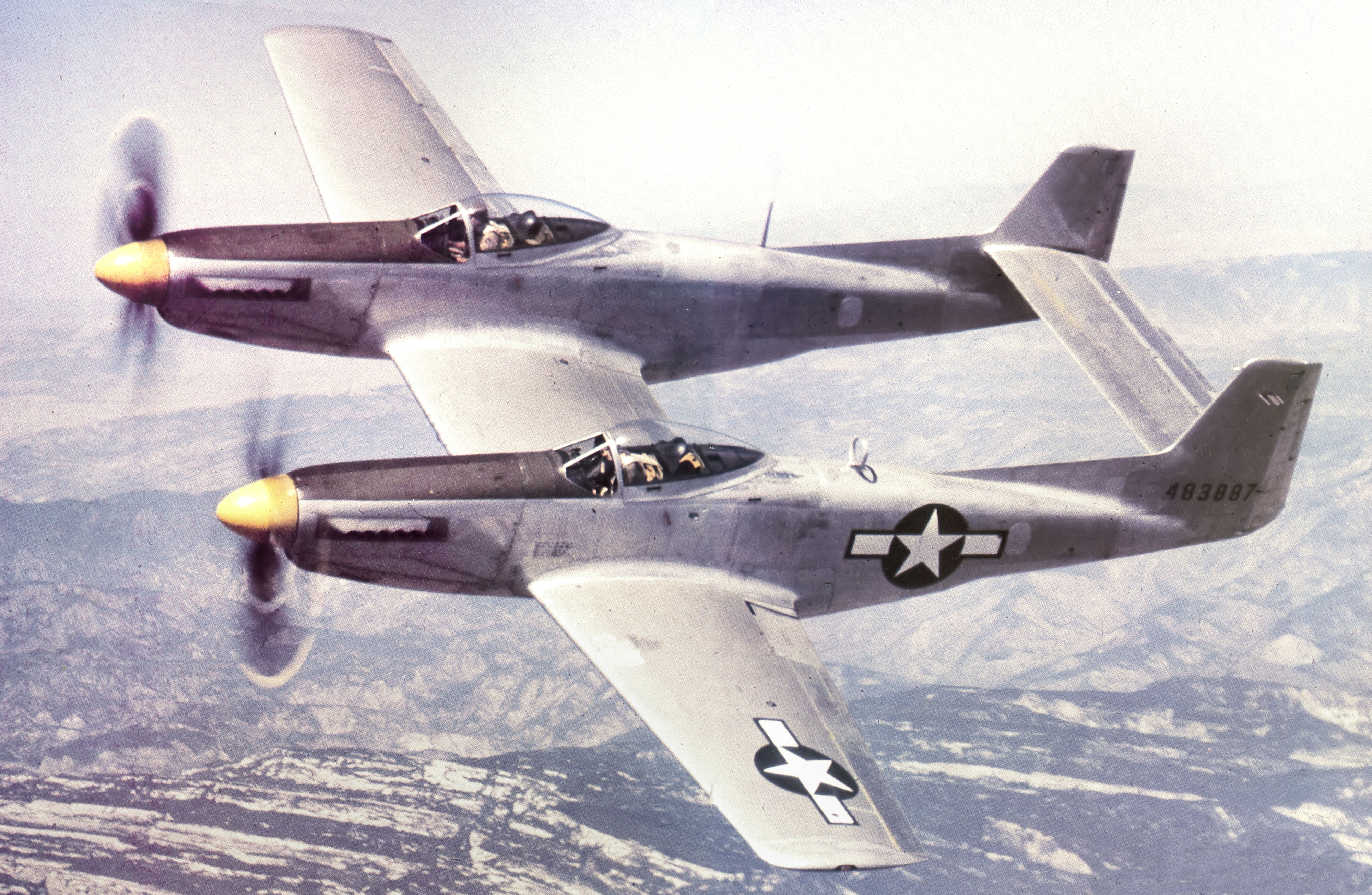
North American XP-82 Twin Mustang 44-83887 in 1945
WarbirdsNews has received the latest XP-82 Twin Mustang restoration update from Tom Reilly at his workshop in Douglas, Georgia. Here’s what they’ve been up to this past month!
Fuselages
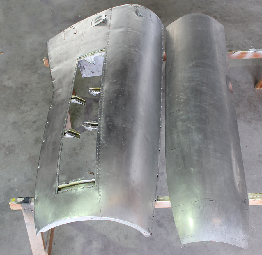
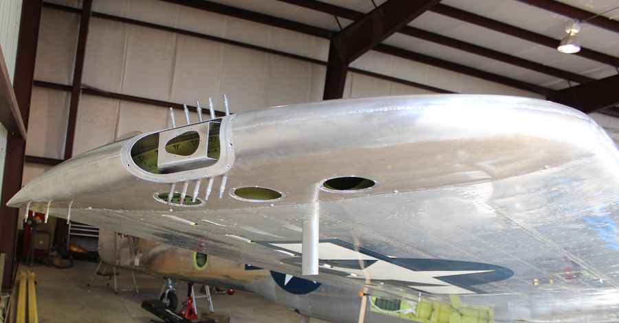
The team has spent a lot of time final-fitting the rotating carburetor air temperature mechanisms, along with the air intake lips and the four side panels.
Lower carburetor air intake chin cowl. (photo via Tom Reilly)Carburetor air control housing assembly and rotating internal barrel. ((photo via Tom Reilly)
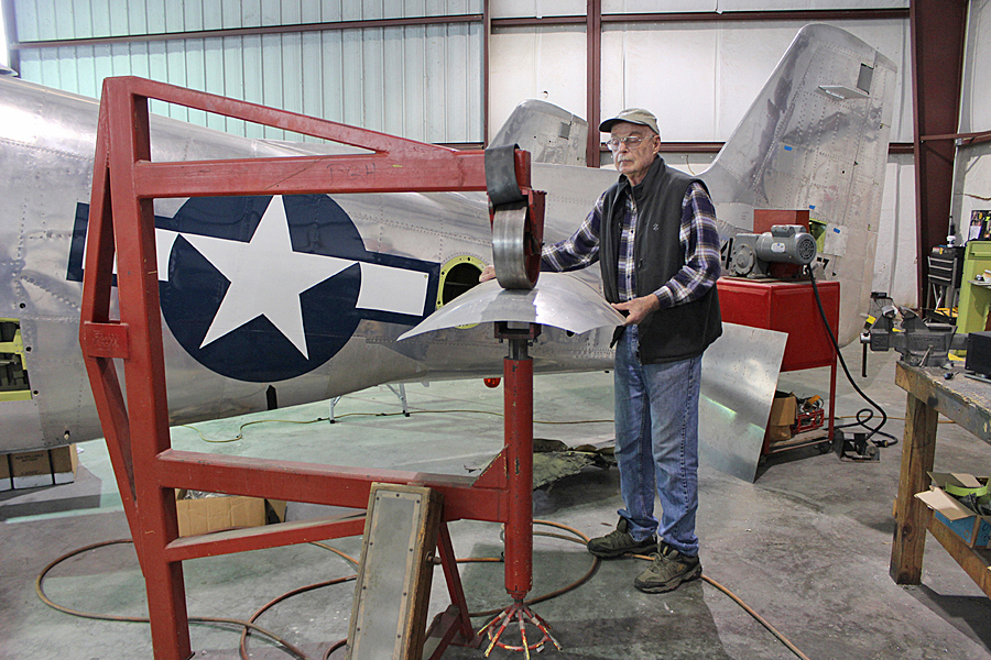
As mentioned last month, all of the lower and side engine cowling panels are now completed. The final shrinking/stretching, English wheeling and Yoder hammer forming of the top two, right-hand engine cowlings will be completed during January. The left-hand, top panel for the right-hand engine is now final-formed and fitted. The right-hand top panel still needs a little more stretching and wheeling.
Tom Reilly working his magic on the English wheel. (photo via Tom Reilly)A completed cowling panel (left) beside the newly wheeled skin for its counterpart to its right. (photo via Tom Reilly)
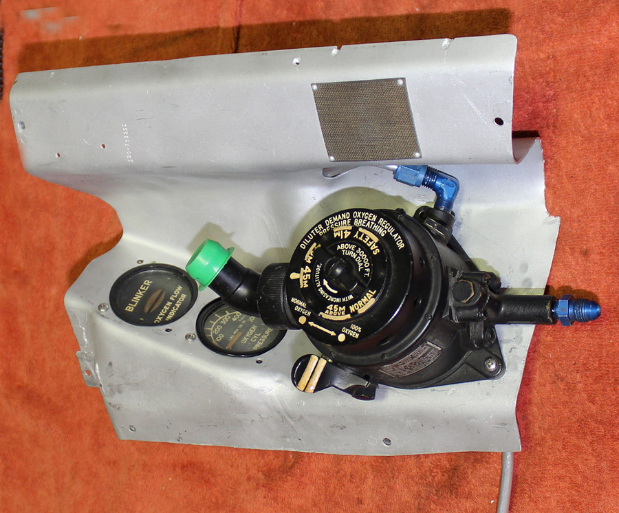
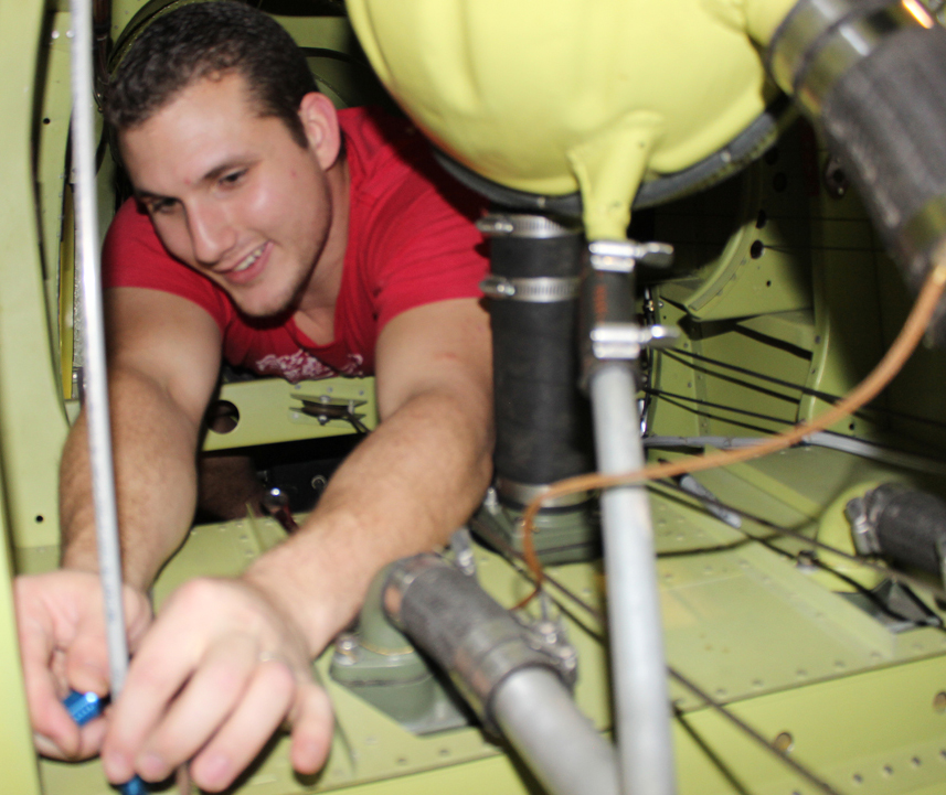
Trying to find the original routing of the oxygen system tubing was a challenge, as all of the available plans show extremely stylized drawings which contradict each other. Thankfully, the restoration crew was able to locate the drilled holes in some of the rejected original side ribs, allowing them to determine the proper location for the line clamps. They were in dramatically different locations to those shown in the stylized drawings. Reilly was also able to source some New Old Stock, four-way Schrader check valves to install, which will help maintain the authenticity of the O2 systems.
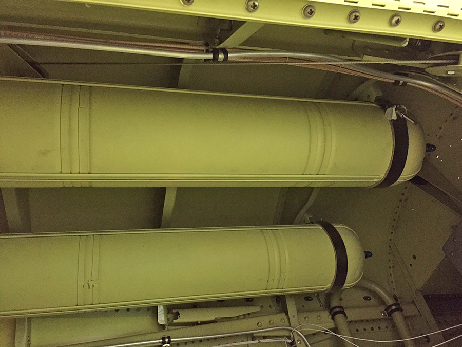
The pilot’s oxygen diluter with its associated gauges mounted to the removable cockpit panel. (photo via Tom Reilly)Routing the oxygen tubing was tight work in places, as is demonstrated ably here by Josh, who is working a line around the coolant header tank. (photo via Tom Reilly)Two small oxygen bottles are mounted in the top forward section of each rear fuselage. (photo via Tom Reilly)The large oxygen bottle mounted in the lower rear of each fuselage. (photo via Tom Reilly)
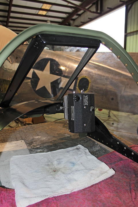
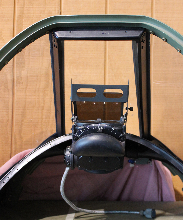
Team members are currently working on how to install the gun sight in the left-hand cockpit and the gun strike camera in the right-hand cockpit, but it is a slow process. Trying to put everything back into this XP-82 exactly as it was on day of its first flight, April 15th, 1945, is excruciatingly time consuming.
The gun strike camera being fitted on the right-hand glare shield. (photo via Tom Reilly)
Gear Doors
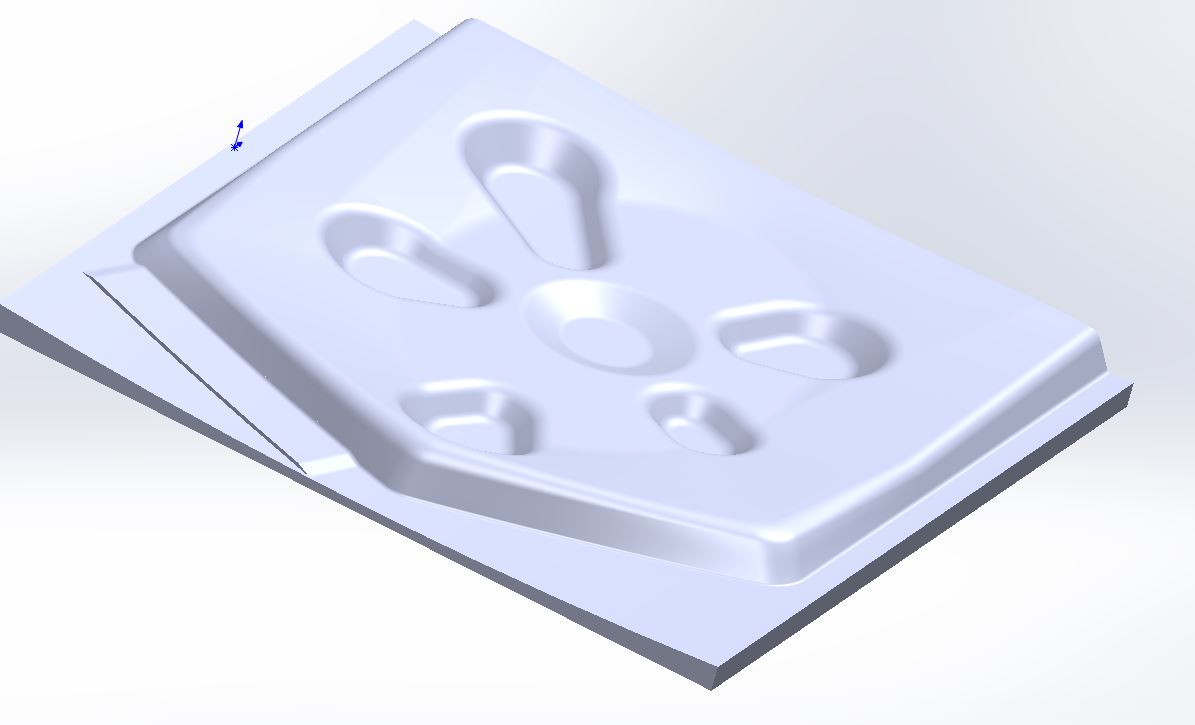
The preliminary forming dies for the main gear center section doors are now complete. The internal pressed skin for each door is a mirror image of the other side. Many hours of machine shop computer work went into these press die patterns. These two center section gear doors are two of the last four major items to complete on the XP-82’s restoration.
A computer generated model of the interior gear door skin. This is used to make an accurate die for forming the new parts. (photo via Tom Reilly)
Control Surfaces
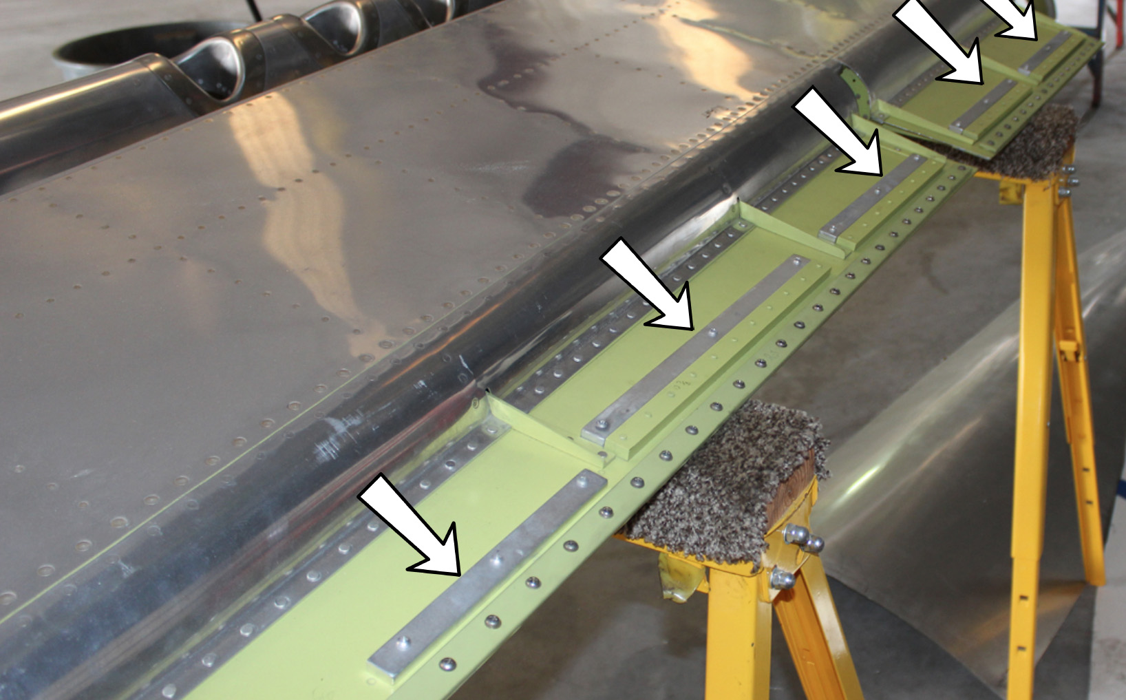
The final balancing of all the control surfaces – the four ailerons, two rudders and one elevator – is now complete. Aircraft control surfaces must be precisely balanced – in accordance with the XP-82 Erection & Maintenance Manual – equal weight forward and aft of the centerline of the hinge points. If they are not balanced properly, they can flutter in flight – much like a flag in heavy wind – and this can lead to catastrophic failure of the part. The restoration team needed to add supplemental leading edge weights to each control surface, because they had replaced all of the hinges, trim tab fittings and trailing edge strips using a much stronger and heavier weight 7075 T6 aluminum alloy in place of the lighter original cast-magnesium components. Trim tab fitting failures due to fluttering in high speed flight have lead to fatal accidents, so getting the correct balance is essential.
The newly installed XP-82 aileron leading edge counterweights denoted by arrows. (photo via Tom Reilly)
Wingtips
Three of the four formed wingtip skins are now finished, with the fourth due due for completion this week. When the parts are ready, the project’s professional welder in Florida will TIG weld (tungsten inert gas) each pair of wingtip halves together. He will match exactly the TIG welding bead pattern of the original wingtips.
(photo via Tom Reilly)(photo via Tom Reilly)
And that’s all of the news for December, 2016!
———————————-
Many thanks again to Tom Reilly for the update! You can learn more about the project on their blog HERE. Please be sure to check back with WarbirdsNews in February, 2017 for the next installment in the story following the XP-82′s road to recovery!
The XP-82 is getting really close to completion! (photo via Tom Reilly)
WarbirdsNews has received the latest XP-82 Twin Mustang restoration update from Tom Reilly at his workshop in Douglas, Georgia. Here’s what they’ve been up to this past month!
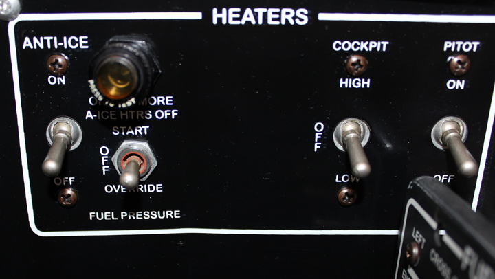
The team has been very busy this past month working to complete the hundreds of small “to-do” tasks that needed finishing, which included the gun sight, completing the 90˚ periscope for the gun strike camera, making heat and defrost, repairing or remaking electrical switch panels, bomb arming panels, fairings that surround the throttle quadrants, a second mounting panel for the oxygen quantity gauge, blinker and diluter valve mechanism, two induction trunk carburetor filtered air boxes, one last 28-volt power supply harness going to the circuit breaker panel, preliminary location for the shielded wiring of the microphone and headset jacks, modifying the shelf underneath the oxygen diluter mechanism to fit the new Garmin radio package, along with the avionics electrical harnesses, etc., etc., etc.
All of these cockpit panels, which Tom Reilly’s restoration crew had to repair or make new, have been shipped off to the printer for silk screening the correct verbage on each panel.
Cockpit panels. (photo via Tom Reilly)The pilot’s radio control panel is now being silk-screened. (photo via Tom Reilly)The 90˚ periscope on the gun strike camera is now installed. (photo via Tom Reilly)The curved, copilot’s circuit breaker panel is currently being silk-screened. (photo via Tom Reilly)The throttle quadrant fairings have been repaired. (photo via Tom Reilly)The gun sight awaiting its mounting bracket. (photo via Tom Reilly)The second mounting panel which contains the oxygen quantity gauge, flow blinker and diluter valve mechanism. (photo via Tom Reilly)
Garmin Radio Package
The project’s avionics specialist came to Douglas with the Garmin radio mounting tray and fitted it into the righthand cockpit underneath the oxygen diluter panel. With a small modification to one rib, the package slotted in perfectly. The microphone and headset jacks will mount in the original locations in the adjoining switch panel to the left of the Bendix Radio panel. And, in the co-pilot’s cockpit, they will mount in the original radio switch panel with the addition of one newly-drilled hole for the headphone jack.
Bendix Remote Control Unit
With much searching, Weezie was finally able to locate this Bendix Remote Control Unit with a collector in California. An extremely rare unit, the last time the team saw one change hands was back in 2006. They were able to purchase this unit only with the express proviso that it was going to be installed in the XP-82.
The ultra-rare Bendix Remote Control Unit for the radio. (photo via Tom Reilly)
Filtered Air Boxes
The last major work ongoing firewall forwards is the manufacture of the two filtered air boxes seen below. The rotating carburettor air valves located under the spinners have four selectable positions: ram air, hot air, half-hot air and filtered air. These are complicated boxes with many angles and shapes that hold the filters for cleaning the air. It will still take two team members about two weeks to complete and fit both units.
The newly-constructed filtered air boxes. (photo via Tom Reilly)
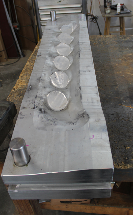
Internal Press Dies for the Main Gear Door Skins
The team’s machinist in Michigan has completed the two huge (350 lbs. each), mirror image press dies shown below, and personally delivered them to Douglas, Georgia on his trip to Florida. Tom Reilly did not want to trust these critical items to a shipping company, as they were very expensive to 3D design and machine, not counting the cost of the two 40” square x 3” thick aluminum plates. The team will take these dies to Atlanta to press-form the gear door skins as their own rubber press is not large enough to handle the exterior dimensions.
The enormously heavy press dies for the inner gear door skins. (photo via Tom Reilly)
And that’s all of the news for January, 2017!
———————————-
Many thanks again to Tom Reilly for the update! You can learn more about the project on their blog HERE. Please be sure to check back with WarbirdsNews in March, 2017 for the next installment in the story following the XP-82′s road to recovery!
North American XP-82 Twin Mustang 44-83887 in 1945
WarbirdsNews has received the latest XP-82 Twin Mustang restoration update from Tom Reilly at his workshop in Douglas, Georgia. This update is a couple of weeks later than usual, as they’ve had a lot on their plate finishing up all of the small, but still-hard-to-do details. So here’s what they’ve been up to this past month and a half!
Lower Cowlings
The final spot-welding on all of the lower cowls is now completed, and the interiors are now painted in the appropriate color.
Here is one of the lower cowlings following the final spot-welding. You can see the many tell-tale dull spots where the two metal sheets were spot-welded together. (photo via Tom Reilly)
Filtered Air Boxes
The filtered air boxes are now also completed and permanently riveted to each forward induction trunk. These filter boxes hold carburetor air inlet filters just in case the aircraft is operated off a dusty or unimproved runway. The filtered air position is selectable by either pilot. Of course, the chance that this XP-82 will ever operate off such a rough strip is probably less than zero, but for authenticity, they had to be installed. (Please note that the camera white balance isn’t quite right in these images, and distorts the true color somewhat.)
A close up view of the filtered air box for the starboard engine. (photo via Tom Reilly)Another view of the starboard engine’s filtered air box. It gives you a strong sense of just how complex this component must be to manufacture! (photo via Tom Reilly)
Antennae
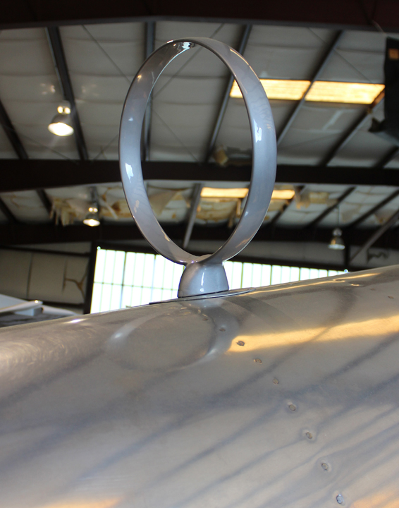
Both the MN-26C Radio Compass ADF Loop and the AN/ARC-3 Radio Antenna Mast are now installed. Tom Reilly wishes to thank Larry Kelley and Bill Saunders for contributing these rare items.
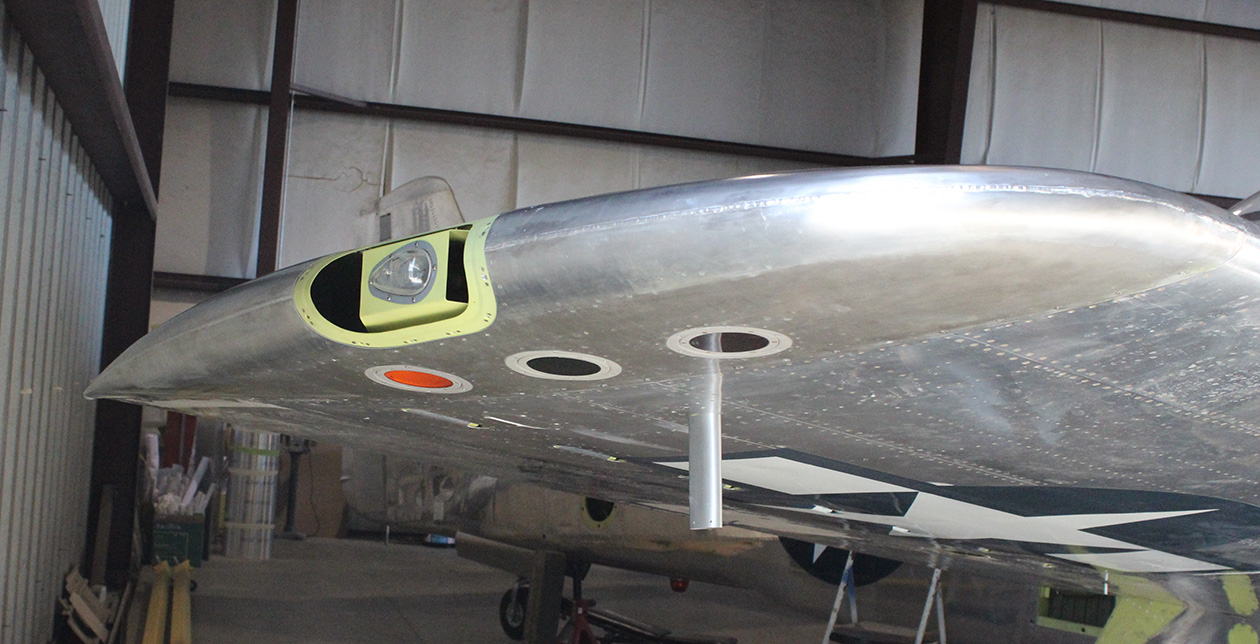
A close up of the ADF loop antenna. (photo via Tom Reilly)Another view of the ADF antenna, showing its position on the port rear fuselage. (photo via Tom Reilly)A photograph of the right rear fuselage showing the location of the AN/ARC-3 radio antenna mast. (photo via Tom Reilly)
Wing Tips
The four wing tip panels, two top and two bottom, are now final fitted. They are just awaiting the welding of their center seams and mounting screw holes and the installation of tip lights and strobes.
The underside of the nearly completed port wing tip. (photo via Tom Reilly)
Cockpits
Both the pilot and co-pilot oxygen regulator/blinker panels, along with the gun sight rheostat are installed. All of the oxygen bottles are now stenciled with the original markings and reinstalled in both fuselages.
The cockpit side wall showing the O2 regulator and blinker as well as the circuit breaker panel in the process of being completed. The breaker panel is awaiting its silk-screened labels to return from a subcontractor. (photo via Tom Reilly)The oxygen bottles are now in place. Note that the stenciling is intentionally inverted to match the original installation. (photo via Tom Reilly)
The K-14 computing gun sight and gun strike camera are now permanently installed. The strike camera presented a problem because the 90º top periscope interfered with the center armor glass since the glass had more sweep back than the P-51 windscreen. The periscope had to be shortened by a ¼” for clearance, as the later camera version had.
The gun strike camera in its position. (photo via Tom Reilly)Th K-14 gun sight. (photo via Tom Reilly)
Main Gear Doors
The frameworks for the main inboard gear doors are now being formed to fit the curvature of the press dies for the inboard door panel. These two inboard doors are one of the last two complex hurdles the team must complete on their XP-82 restoration project.
One of the gear door frames. (photo via Tom Reilly)
Brakes
The last complex items are the two brake calipers. These two brake calipers are now being machined and are expected to be delivered in about two months.
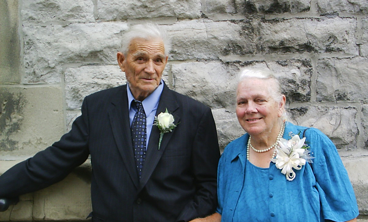
The late Walter and Peggy Soplata, salvors of the XP-82, among many other rare aircraft. Sadly, Peggy passed away recently. You couldn’t hope to meet two sweeter people, and their loss will be felt among the entire vintage aviation community. (photo via Tom Reilly)
Walter & Margaret (Peggy) Soplata
With much sadness we must announce the passing of Margaret (Peggy) Soplata. Walter (who passed six years ago) and Margaret Soplata from Newbury, OH, were the husband and wife team, along with their five children, who saved countless extremely rare warbirds and priceless artifacts from the smelter.
All of the warbird community owes them a debt of gratitude for saving these precious, historic artifacts for us and future generations to enjoy.
A small list of some of the aircraft and parts that the Soplata family saved:
• 2 F4U Corsairs, one 4360-powered FG1
• 2 North American B-25s
• 1 B-36 Peacemaker
• C-97 and C-82 Fuselages
• 1 A-26 Invader
• 2 TBM Avengers
• 1 P-63 King Cobra
• 1 AD4 Skyraider Prototype
• 2 F86 Sabres
• 1F7U Cutlass
• 2 T-28s
• 1 Victor Cockpit
• 1 SNJ – 7
• 1 XP-82 Twin Mustang Prototype/1 F-82E Twin Mustang
• 1 BT-13
• A rare snow-ski configured P2V Neptune that is the lone survivor of an epic
Navy expedition to explore Antarctica in the 1950s
• 1 partial F4U fuselage
• T-33 and F100 cockpits
• A number of V-12 Merlins, Allisons and radial engines
• Numerous cutaway display engines
• Countless propellers, starters, generators, magnetos, and antique WWII radios
• Countless other aviation-related artifacts
Many thanks again to Tom Reilly for this update. You can learn more about the project on their blog HERE. Please be sure to check back with WarbirdsNews in April, 2017 for the next installment in the story following the XP-82′s road to recovery!
WarbirdsNews has received the latest XP-82 Twin Mustang restoration update from Tom Reilly at his workshop in Douglas, Georgia, and we thought you would all be pleased to see the latest progress!
Wing Tips
After what seems like forever, the forming and welding of the seams on the two wing tips are now completed with the exception of their final spot welding. The Lucite (Plexi-glass) red and the green lenses that cover each tip light bulb still need to be formed.
The left-hand wing tip. Notice also the mount for the wing tip light. (Photo via Tom Reilly)The right-hand wing tip with tip light mount and three holes on the wing underside for the identification lights. (Photo via Tom Reilly)
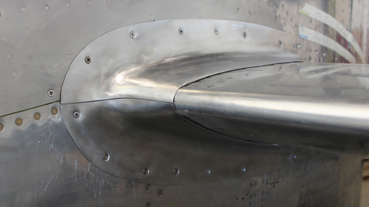
Tail and Wing Fairings
The left and right horizontal-to-vertical stabilizer fairings are now complete, less the welding on the leading edge seams. They have a unique mounting. Each fairing screws horizontally to the vertical stabilizer and dorsal panel, but only rubs on a thin phenolic strip mounted to the upper and lower surfaces of the horizontal stabilizer. There are no vertical attaching screws.
The left hand horizontal stabilizer fairing prior to welding the seam. (Photo via Tom Reilly)The right hand horizontal stabilizer fairing prior to welding the seam. (Photo via Tom Reilly)
The forming of the fuselage-to-wing/center section and trailing edge fairings has just got underway.
Top Cowlings for Right-hand Engine
The right-hand top cowl for the right-hand engine has now finally been reworked, fit and drilled to the internal framework. The left-hand top cowl is still presenting such a challenge that Tom Reilly thinks they will have to remake the entire panel. He states that it has been quite a frustrating job to try to correct these two top panels.
The right hand top cowl after much rework. (Photo via Tom Reilly)
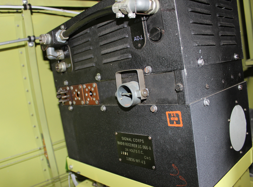
Original WWII Radios
The final original radio receiver, a BC-966-A, has been installed completing the entire radio package. The team also found a rare detonator switch that was designed, in the event of a high-G crash, to trigger an explosive charge mounted in each radio thereby destroying it and preventing an enemy from gaining any knowledge. Of course, all of the XP-82 radios have not had these charges installed.
The BC-966-A Receiver, the last original radio needing installation. (Photo via Tom Reilly)
The detonator impact switch. (Photo via Tom Reilly)
The team also has original Cannon plug connectors for each radio that still need to be wired for authenticity.
The latest Garmin radio and avionics package was being installed as these words were written.
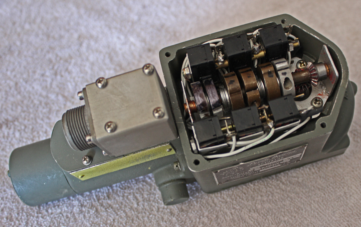
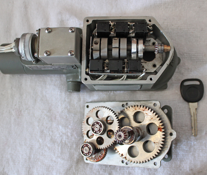
Carburetor Air Temperature Control Motors
These two motors, with their microscopic armatures, field windings, micro-switch wiring, 90° gearing and switch rollers are almost complete. The left-hand motor has been finished for about two weeks now. Reilly expects to have the final backlash fitting of the two 90 degree gears in the right-hand motor completed next week and both motors finally installed in the engine compartments.
One of the Carburetor Air Temperature Control Motors with it’s protective lid removed. (Photo via Tom Reilly)Another image of a Carburetor Air Temperature Control Motor with it’s protective lid removed beside a reduction gear assembly. (Photo via Tom Reilly)(Photo via Tom Reilly)
Screen-printed Panels
All of the screen-printed panels have now been fitted with their switches, rheostats, lights, push buttons, etc., and mounted in their respective positions in each cockpit.
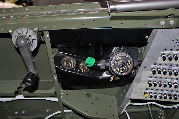
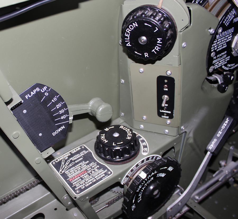
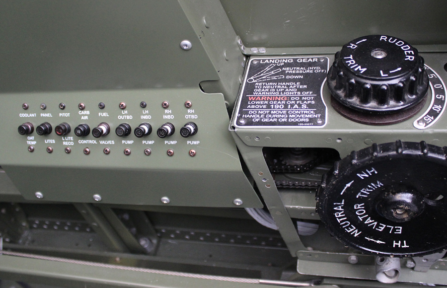
The left cockpit flap handle, aileron trip, landing light switch, rudder trim, elevator trim and gear handle. (Photo via Tom Reilly)
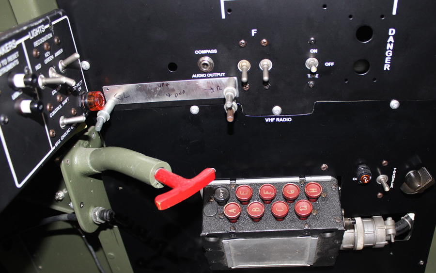
The radio channel selector alongside the Emergency Gear Uplock Release Pull Handle in the right hand cockpit. (Photo via Tom Reilly)
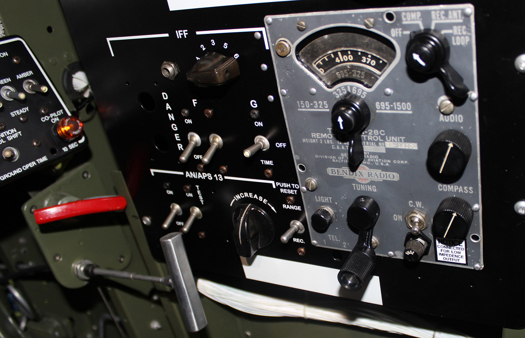
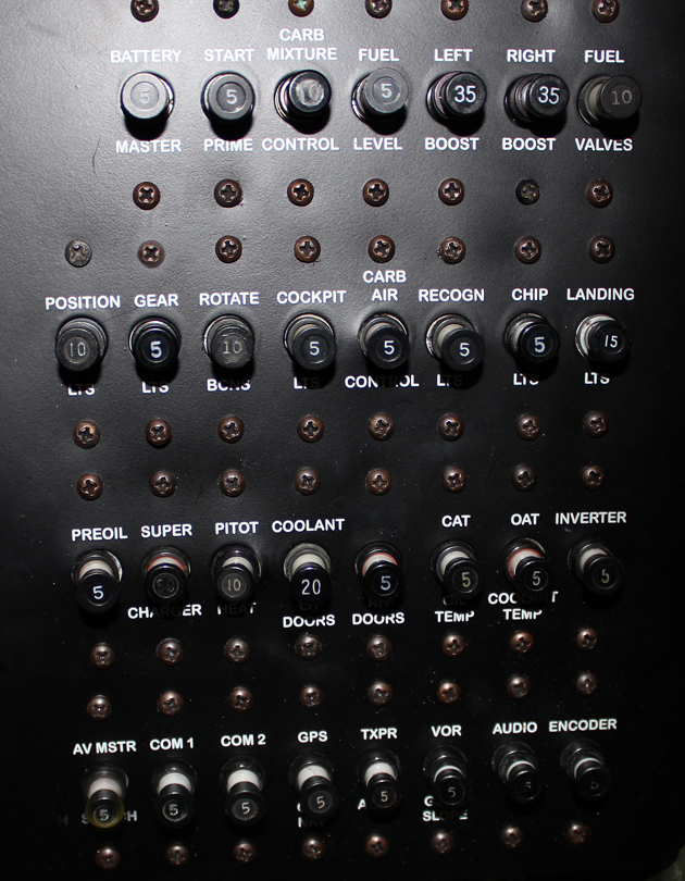
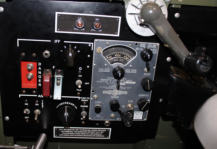
The Bendix Radio Remote Tuning Unit MN-28-C. The red handle is the emergency landing gear up-lock roller(s) and gear door hook(s) releases (Pilot’s cockpit). (Photo via Tom Reilly)The pilot’s main circuit breaker panel. (Photo via Tom Reilly)The co-pilot’s circuit breaker panel. (Photo via Tom Reilly)The pilot’s left hand switch panel. (Photo via Tom Reilly)The co-pilot’s left-hand switch panel. (Photo via Tom Reilly)
Gear Retractions
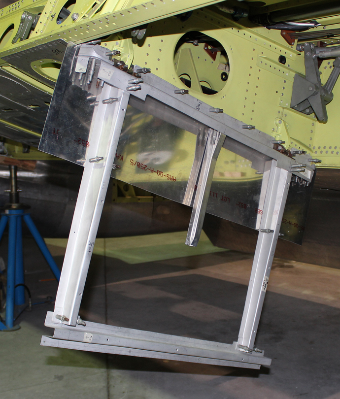
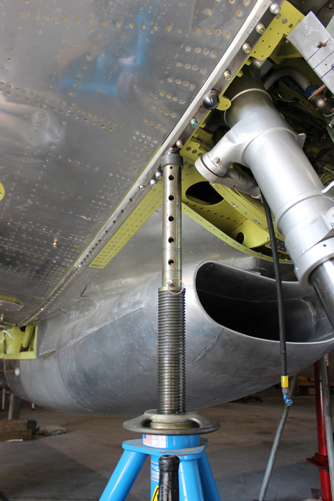
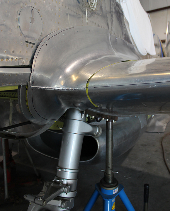
Tom Reilly chose to make two special steel mounting plates that attach with internal wrenching bolts to and through each lower wing attach angle. Each jack mounting plate has two male sockets, one adjacent to the center section main spar used for jacking the aircraft for gear retractions, and a second one next to the main landing gear for the weight-and-balance pick-up point. Both steel mounting plates are removable after the retractions and weight-and-balance calculations.
The undercarriage jack plate visible in this shot during the undercarriage trials. (Photo via Tom Reilly)A detailed view of the jack plate. (Photo via Tom Reilly)
The restoration team has now filled the XP-82 hydraulic system with 14 quarts of Mil H 5606 hydraulic fluid, and is proceeding with the gear retraction tests.
Much time is being spent adjusting the twelve push-pull rods which activate each inboard gear door forward and aft up-lock hooks along with the emergency up-lock release and hook pull cables.
And that is all for this month’s report.
Many thanks again to Tom Reilly for this update. You can learn more about the project on their blog HERE. Please be sure to check back with WarbirdsNews in May, 2017 for the next installment in the story following the XP-82′s road to recovery!
F-82E Twin Mutstang at Adak Island, Alaska, 1948. United States Air Force via Wings magazine – October 2003 edition “Alaska Twin Mustangs”
WarbirdsNews has received the latest XP-82 Twin Mustang restoration update from Tom Reilly at his workshop in Douglas, Georgia, and we thought you would all be pleased to see the latest progress!
Electrical
The restoration team is in the last phases of testing each electrical circuit. These are quite complicated systems in the XP-82 and also the first twenty B-model Twin Mustangs, which all had full dual controls. Each pilot had the ability to switch all electrical controls back and forth between each cockpit, i.e. boost pumps, fuel shut-offs, cross-feeds, all lighting, electronic mixture controls, coolant door motors, carburetor air temperature motors, generators, bombs, rockets, guns and superchargers. The transfer of electrical control was effected by selecting certain switching relays.
This unique ability to switch electrical control from pilot to co-pilot or vice versa was necessary because the Twin Mustang had a 12-hour plus range with external fuel. It allowed pilots to take turns resting on long missions. As an example of extreme endurance in a Twin Mustang, Col. Robert Thacker flew ‘Betty Jo’, a Merlin-powered P-82B, non-stop from Hickam Field, Hawaii to LaGuardia Airport, New York in 14.5 hours on February 27th, 1947. Thacker is still living today at the tender age of 100!
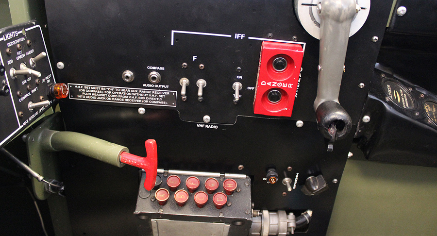
Tom Reilly finally found the last of the two electrical components necessary to complete the original radio installations. The impact detonator switches are now installed in both cockpits. These devices could be activated by either pilot prior to bailing out in order to ensure destruction of the then top secret IFF radios when the abandoned aircraft crashed.
The copilot’s radio package. Note the impact destruct switch (the red panel with two black buttons). (photo via Tom Reilly)Pilot’s radio package. Note the impact destruct switch (the red panel with two silver buttons). (photo via Tom Reilly)
Fuselage Fairings
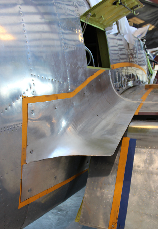
Most of the months of April and May have been spent English-wheeling skins for the fuselage-to-center section and fuselage-to-outboard wing trailing edge and wing fairings. Quite a number of complicated special curvatures had to be wheeled into the trailing edge fairings that do not show in the pictures. All four fairings are temporarily fit prior to final trimming.
The lefthand inboard fuselage-to-center section fairing in place during trial fitting. (photo via Tom Reilly)The righthand inboard fuselage-to-center section fairing in place during trial fitting. (photo via Tom Reilly)The lefthand outboard fuselage-to-center section fairing in place during trial fitting. (photo via Tom Reilly)The righthand outboard fuselage-to-center section fairing in place during trial fitting. (photo via Tom Reilly)
The team has just started forming the four compound curved leading edge fairings that go from the fuselages to the center section and fuselages to the outboard wings.
English wheeling one of the fairings. (photo via Tom Reilly)
Top Engine Cowling
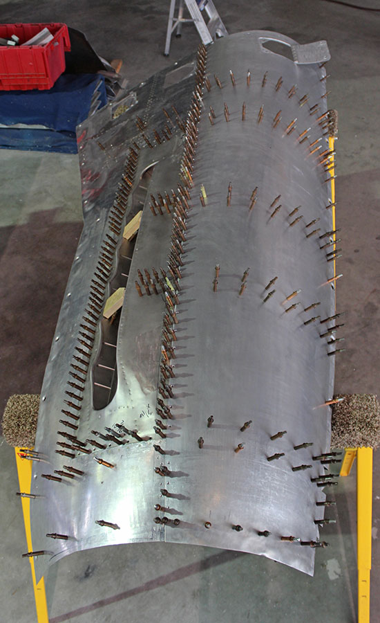
Prior to spot-welding, the tack riveting of the top right cowl for the right-hand engine is now being completed. The solid rectangular line of clecos shown in the picture is holding in the stainless exhaust trough. These will be filled with rivets as spot-welding will not attach stainless steel to aluminum. The opposing left-hand top cowling panel requires refabrication.
An interior view of the top right cowl for the right-hand engine during the tack-riveting process. Clecos are holding the ribs in place at this point. (photo via Tom Reilly)An exterior view of the top right cowl for the right-hand engine during the tack-riveting process. Clecos are holding the ribs in place at this point. (photo via Tom Reilly)
Hydraulic System
The hydraulic system tests for the landing gear and flaps should be completed by the end of June.
Control Systems
The final rigging of range movements for the primary flight control cables for both the elevator and rudders is now completed, along with their associated trim tab systems.
When the outboard wings are fully attached, the final rigging for the ailerons and trim tab will take place.
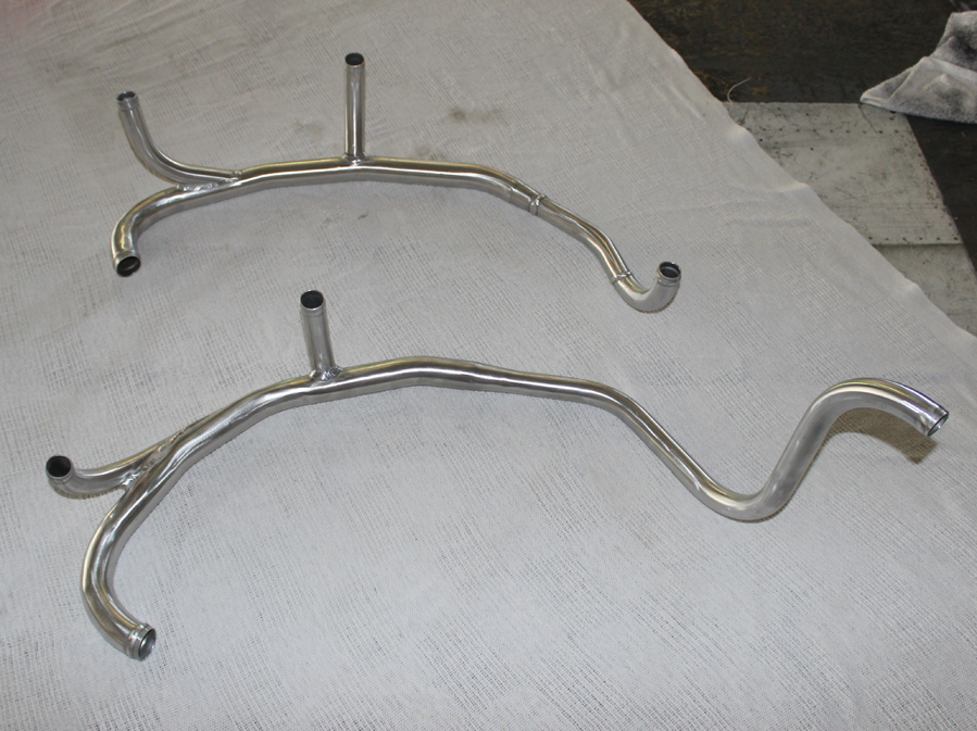
Firewall Forward
Engine crankcase vent tubes that are attached to each valve cover and the nose case vent port are now completed. (photo via Tom Reilly)
And that is all for this month’s report.
Many thanks again to Tom Reilly for this update. You can learn more about the project on their blog HERE. Please be sure to check back with WarbirdsNews in June, 2017 for the next installment in the story following the XP-82′s road to recovery!
North American XP-82 Twin Mustang 44-83887 on a test flight over the Sierras in 1945.
WarbirdsNews has received the latest XP-82 Twin Mustang restoration update from Tom Reilly at his workshop in Douglas, Georgia, and we thought you would all be pleased to see the latest progress!
Since the project is coming very close to completion, there are fewer and fewer major accomplishments that can be photographed. Therefore project updates will now come every two or three months following this edition.
Top Engine Cowlings
Casey Hill, one of two English wheel subcontract wizards working on the project, came down for three days to help on the fairings. Tom Reilly pointed out the non-fitting top right-hand engine cowl to him and asked if he could do anything with it. It took him and Paul a day, and the two of them had it fitting perfectly. The team should have this left-hand top cowl completed within the next two weeks.
Left top cowling, exterior view. (photo via Tom Reilly)Left top cowling, interior view. (photo via Tom Reilly)
Fuselage Fairings
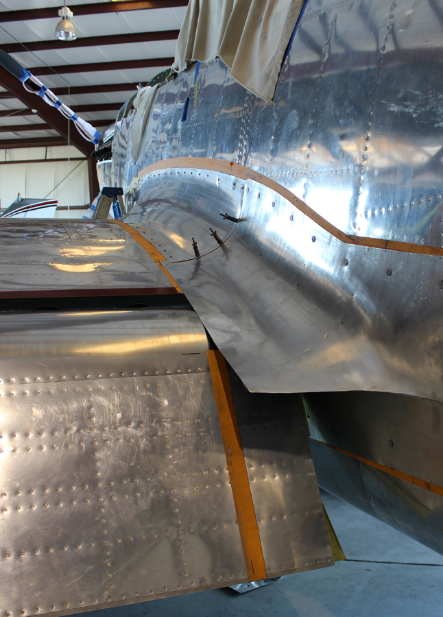
All of the outboard fuselage-to-wing fairings, from leading edge to trailing edge, are now complete. The team finished the final seam welding of the two outboard forward fairings this past week. Only the two lower halves for the inboard side of each fuselage-to-center-section fairing still need work.
Paul, the project’s lead sheet metal team member, has done a wonderful job by learning these English wheel and Yoder hammer sheet metal techniques, with the help from Rick Reeves, the XP-82’s other English wheel subcontract wizard. These have been very difficult pieces to form, but they have come out beautifully. In one more week, Paul will have the two bottom halves completed, awaiting seam welding. Then all of the XP-82’s fairings will be done.
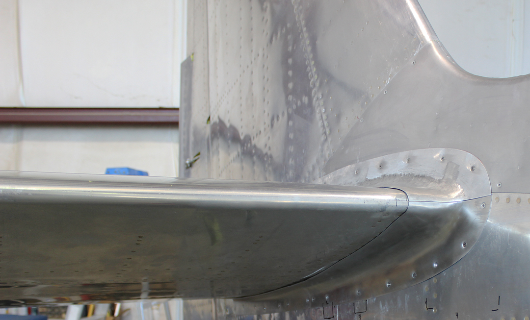
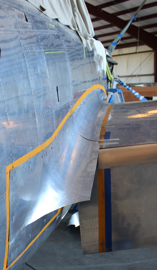
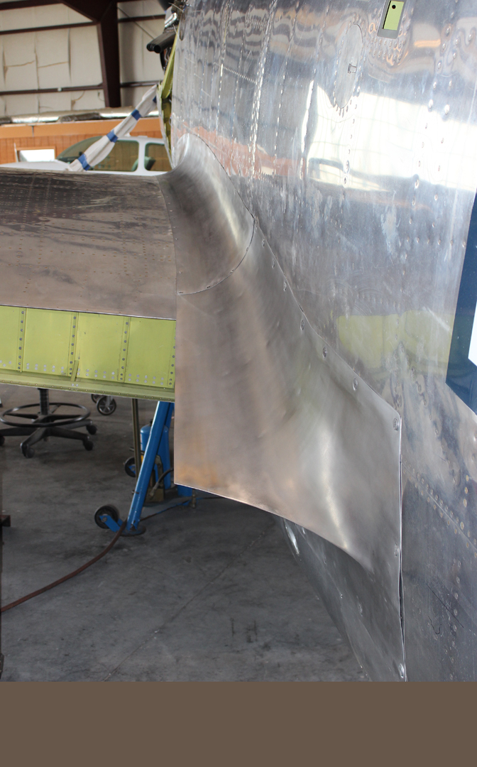
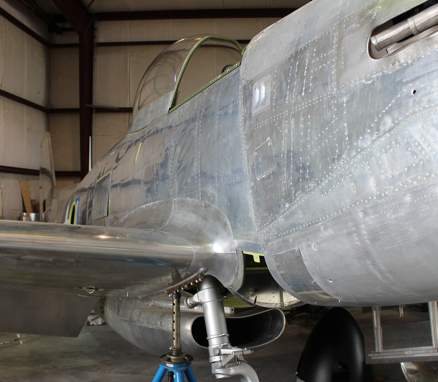
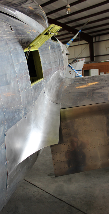
Outboard fuselage to wing leading edge fairings. (photo via Tom Reilly)The right hand, leading edge outer wing root fairing during trial fitting. (photo via Tom Reilly)The left hand, leading edge outer wing root fairing during trial fitting. (photo via Tom Reilly)
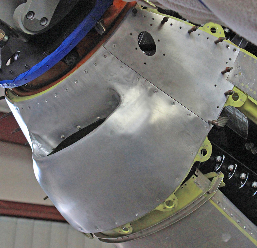
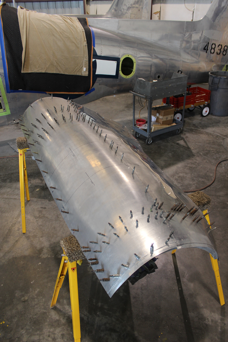
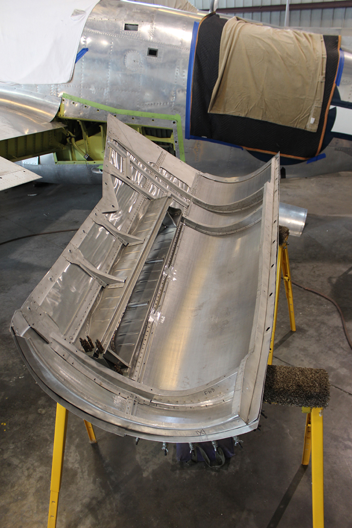
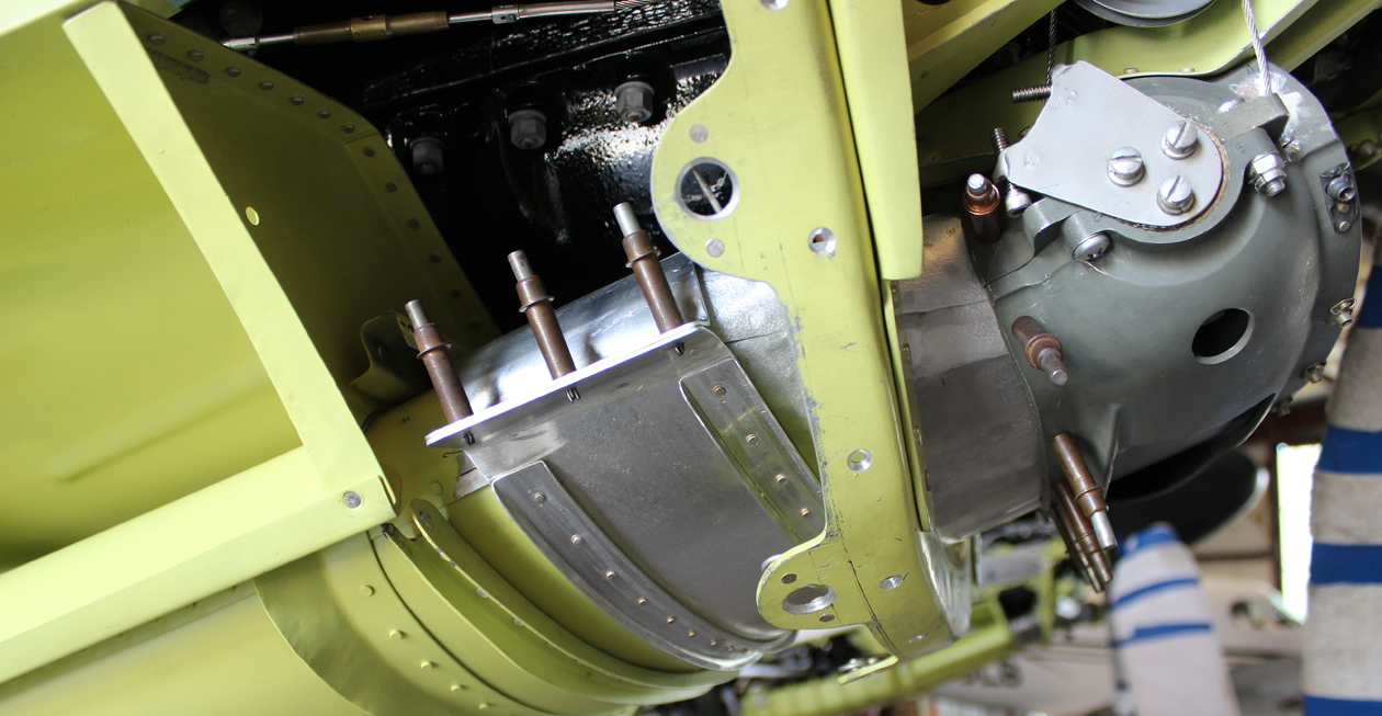
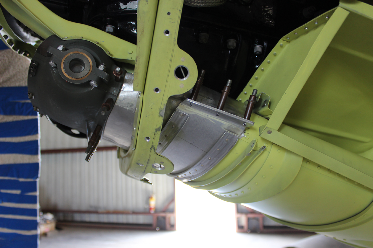
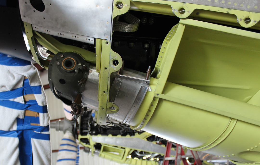
Lower Chin Cowl to Air Induction Trunk Adapters
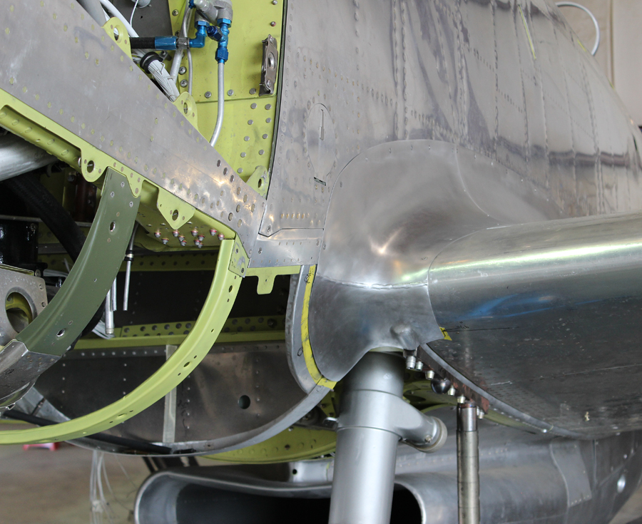
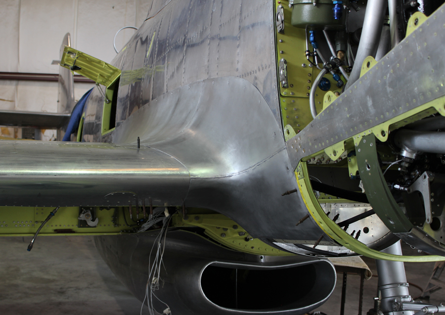
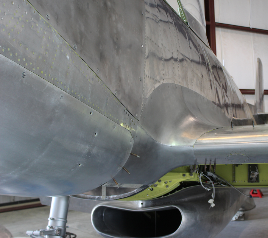
Randall and Paiden have accomplished in two weeks what Tom Reilly expected would take at least a month: forming the two adapters that join the chin cowls to the air induction trunks as well as the adapter covers to rubber seal these two removable joints. The parts have extremely complex compound curves, which is what makes them so difficult to replicate by hand, but they are now almost ready for final installation. The only remaining thing to do is to install the rubber for the seals (presently on order).
The right hand engine’s lower chin cowl to air induction trunk adaptor, seen from the right side. (photo via Tom Reilly)The right hand engine’s lower chin cowl to air induction trunk adaptor, seen from the left side. (photo via Tom Reilly)The left hand engine’s lower chin cowl to air induction trunk adaptor, seen from the right side. (photo via Tom Reilly)The left hand engine’s lower chin cowl to air induction trunk adaptor, seen from the left side. (photo via Tom Reilly)
Electrical
Two team members have been completing and checking out each electrical system, one circuit at a time. Every circuit is now proven, except for one wire on one coolant door motor, two rotating beacon resistors, and the entire up/down landing gear circuit. Within the next two weeks Tom Reilly expects to have the remainder of the electrical system completed.
Exhaust Fairings
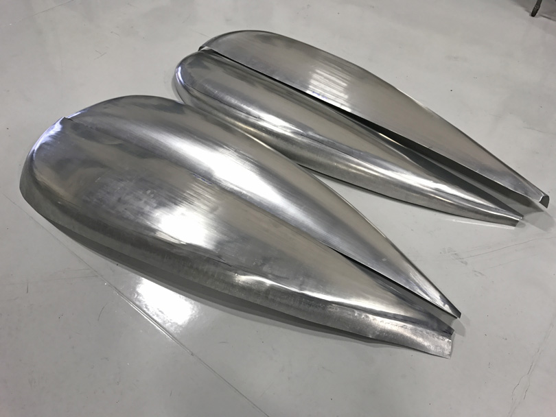
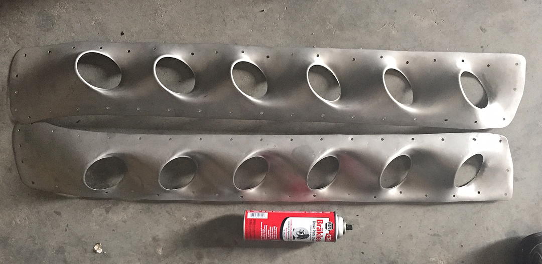
When Tom Reilly collected the XP-82 from Walt Soplata’s farm, he found only two of the four exhaust fairings required. These secondary stainless steel exhaust fairings only fit the P-51 H Mustang and the first 22 Merlin-powered P-82s. The restoration team has scoured the earth, and surrounding planets, for a spare pair of these exhaust fairings, but none could be found. There are only three H-model Mustangs still flying, and their owners have no clue where extra fairings could be sourced.
Remanufacture of these fairings is very difficult in part because of the complex shape, but also due to the heavy gauge (.050″) of the sheet stock required and the very sharp-edged detail around each exhaust port. Thus the project has had to have to have a pair of aluminum male and female press dies (four) machined to form the replacement fairings. The team has sent one of these two mirror image exhaust fairings to a subcontract machine shop to have it 3D printed, as the computer can easily flip the orientation of the virtual part to create its mirror for 3D printing.
The stainless steel engine exhaust fairings. (photo via Tom Reilly)
Avionics Package (Garmin)
The Garmin radio package has arrived and the team will begin installation sometime in July.
Man (and woman) hours spent on the XP-82 restoration to date
Tom Reilly states that his team of workers, subcontractors and volunteers, etc. has put over 173,000 hours of labor into the XP-82’s restoration over the past nine years. In contrast, North America Aviation’s engineering and fabrication teams put 1,462,190 hours into the design and manufacture of the first XP-82 up to and including its first flight. That aircraft was 44-83887, the very same Twin Mustang which Reilly and his team have been working so hard to bring back to life…
And that is all for this month’s report.
Many thanks again to Tom Reilly for this update. You can learn more about the project on their blog HERE. Although we are not exactly sure when the next formal update will come, please be sure to check back with WarbirdsNews in a couple of months for the next installment in the story following the XP-82′s road to recovery!
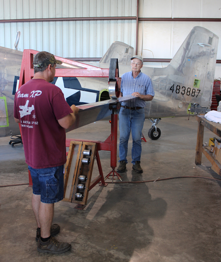
The project’s XP-82 Twin Mustang during live-fire trials of the experimental, eight gun, machine gun pod (at the same time as the six internal .50 machine guns mounted inside the center wing section). With the addition of this pod, the XP-82 had a massive total of 14 forward-firing .50 caliber Browning M3 machine guns! Note the pile of spent shell casings massing on the concrete floor! (photo via Tom Reilly)
WarbirdsNews has received the latest XP-82 Twin Mustang restoration update from Tom Reilly at his workshop in Douglas, Georgia, and we thought you would all be pleased to see the latest progress! As we mentioned in our last update in early July, since the project is coming very close to completion, there are fewer major accomplishments that can be photographed, which means that our usual monthly reports will happen more infrequently, hence the two month gap since the last posting. This does not mean that plenty isn’t happening on the resurrection of XP-82 Twin Mustang 44-83887, just that only some of it can be documented easily.
The project’s XP-82 Twin Mustang during her trials with the experimental, center-mounted machine-gun pod. (photo via Tom Reilly)
Fuselage Fairings – Inboards and Outboards
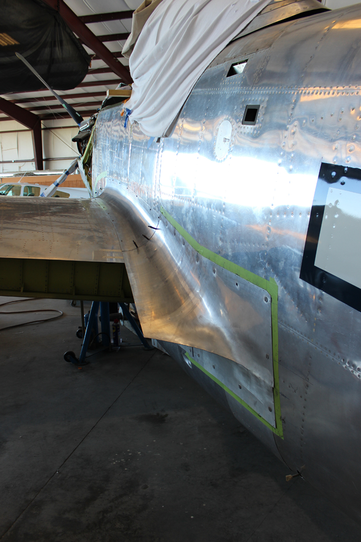
All of the fairings are now completely finished. The final task for each of the twelve fairings was to polish out the microscopic English wheel roller marks. Each fairing has had its mounting holes drilled. All of the edges have been trimmed to match and all are now completely fit and installed.
The left-hand inboard trailing edge fairing. (photo via Tom Reilly)The left-hand outboard leading edge fairing. (photo via Tom Reilly)The left-hand inboard leading edge fairing. (photo via Tom Reilly)The right-hand inboard leading edge fairing. (photo via Tom Reilly)The right-hand inboard trailing edge fairing. (photo via Tom Reilly)The right-hand outboard leading edge fairing. (photo via Tom Reilly)The right-hand outboard trailing edge fairing. (photo via Tom Reilly)
Top Engine Cowls
Both top cowls (right-hand engine, left and right) are completely riveted, spot-welded together and now undergoing final polishing and edge trimming. They have been a challenge, to be sure, but have finished out very well.
The left-hand top engine cowling panel for the right hand engine in place during the test-fitting and trimming phase. (photo via Tom Reilly)A rear view of the right hand upper engine cowling for the right hand engine during the fitting/trimming stage. (photo via Tom Reilly)A view of the right hand upper cowling for the right engine during the test-fitting and trimming phase. (photo via Tom Reilly)
Spot Welding
Tom Reilly sent both of the newly-manufactured, right-hand, engine top cowlings to Kermit Weeks’ facility in Polk City, Forida, for spot welding. Rick Reeves, the man that helped form many of the project’s parts, did the job using Kermit’s state-of-the-art spot welding machine.
Electrical
Every electrical system in the XP-82, with the exception of the landing gear position wires, has been checked under power. The massive number of wire harnesses in each cockpit is now being tie-cord wrapped (aviation cord instead of tie wraps).
The Instrument Panel Covers
The aluminum closeout panels which cover the top of each instrument panel are now complete.
The newly-fabricated cockpit instrument panel close-out covers. (photo via Tom Reilly)
Hydraulics/Landing Gear
The project had some timing issues with both the landing gear and flap actuating valves, but they have now been adjusted and hydraulically evaluated on the test bench. They now check out perfectly, and are due to be installed this week in order to start the gear retraction tests.
Tail Gear Doors
Tom Reilly received the four tail gear door inner pressings from Pat Harker in Anoka, Minnesota. Harker had male and female press dies machined to allow the manufacture of new inner tail wheel waffle skins for his own F-82E Twin Mustang project, and generously made a set of new skins for the XP-82’s tail wheel doors as well.
The tail wheel gear doors mounted in place during the test-fitting. (photo via Tom Reilly)Original tail wheel gear door. (photo via Tom Reilly)
The XP-82 restoration team has just completed fitting all four tail wheel doors. On Tom Reilly’s next trip to Florida, he will have the outboard skins spot welded to the inboard waffle skins.
New tail wheel gear door waffle skins awaiting spot welding. (photo via Tom Reilly)
Inboard Main Gear Doors
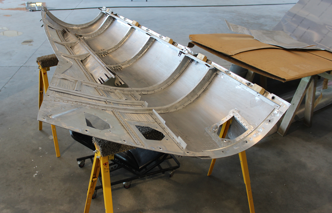
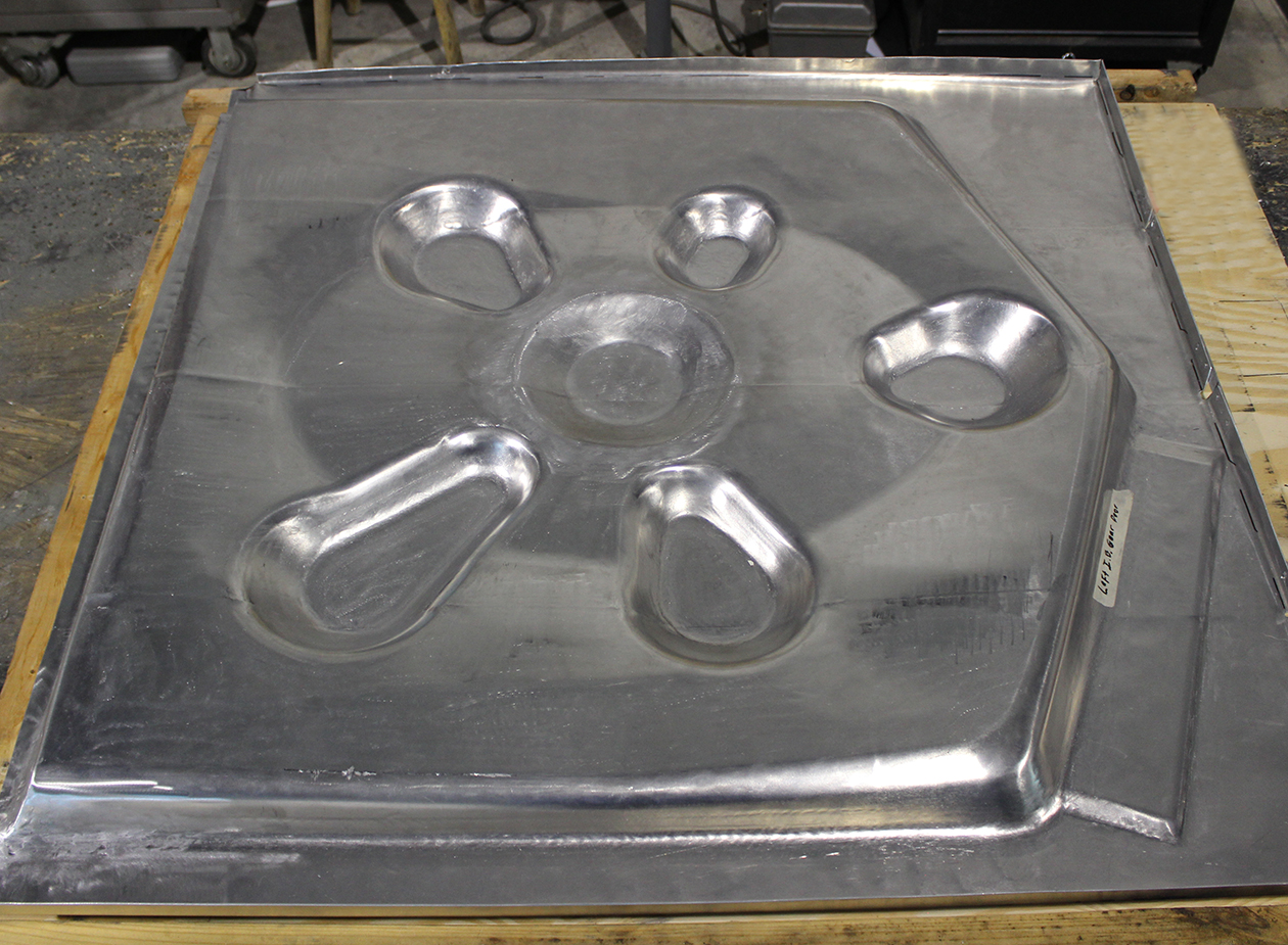
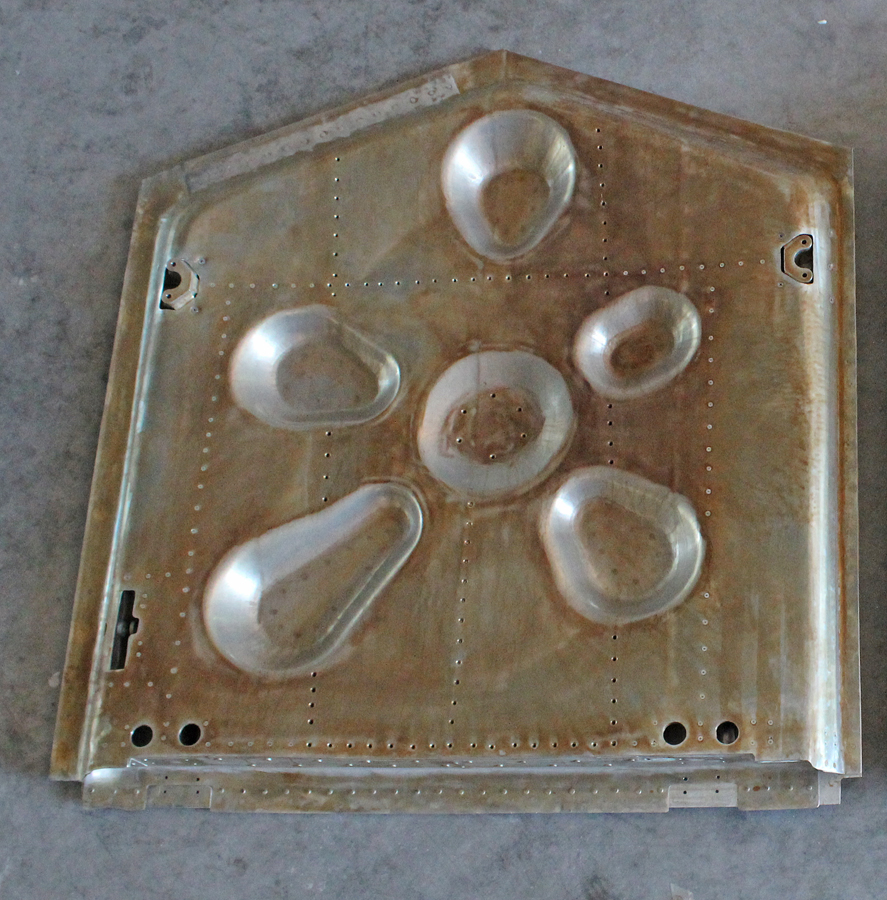
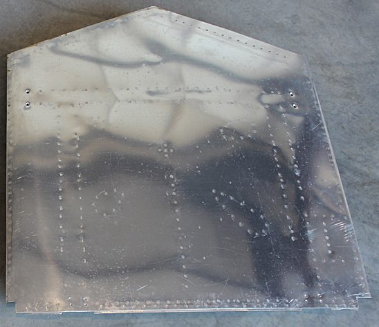
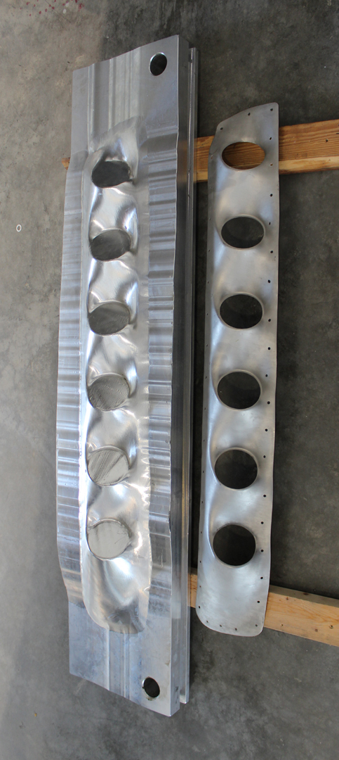
This week the restoration team started pressing the interior waffle skins over machined aluminum press dies for the inboard main gear doors (36” x 42”). These inside skins are formed from .063″ thick, untempered 2024 aluminum sheet, and have a 2″ depth on each of the six pressings. They were formed by “flow forming”, using soft hammers and wooden blocks for the close radiuses.
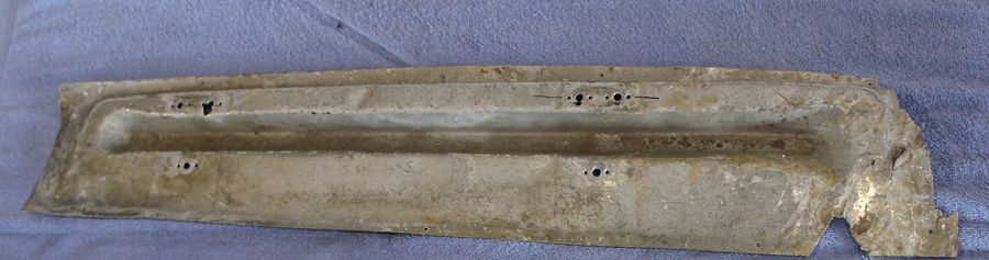
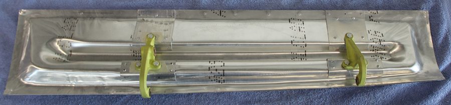
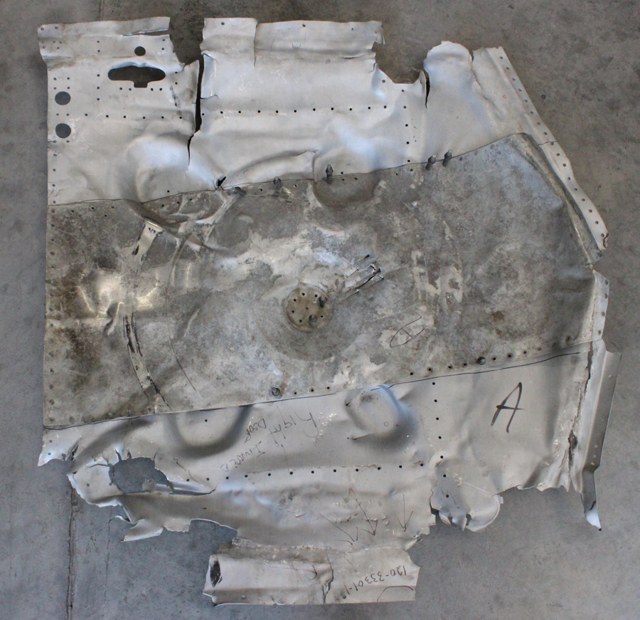
The heavily damaged original gear door inner skin which Reilly’s team used as a template to create new examples. (Photo via Tom Reilly)The two internal gear door skins are now completed awaiting final fitting, trimming, heat treating. riveting to the internal framework and spot welding. (photo via Tom Reilly)
And that is all for this month’s report.
Many thanks again to Tom Reilly for this update. You can learn more about the project on their blog HERE. Although we are not exactly sure when the next formal update will come, please be sure to check back with WarbirdsNews in a couple of months for the next installment in the story following the XP-82′s road to recovery!
Tom Reilly getting settled into the pilot’s seat for the engine run-up on October 17th! (photo via Tom Reilly)
WarbirdsNews has received the latest XP-82 Twin Mustang restoration update from Tom Reilly at his workshop in Douglas, Georgia, and we thought you would all be pleased to see the latest progress! As we mentioned in our last update in early July, since the project is coming very close to completion, there are fewer major accomplishments that can be photographed, which means that our usual monthly reports will happen more infrequently, hence the two month gap since the last posting. This does not mean that plenty isn’t happening on the resurrection of XP-82 Twin Mustang 44-83887, just that only some of it can be documented easily. This restoration update will mostly consist of a photo-essay with captions to show which areas have been receiving attention most recently.
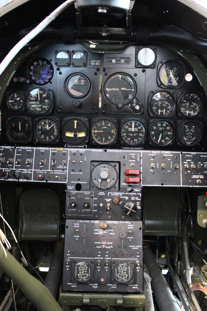
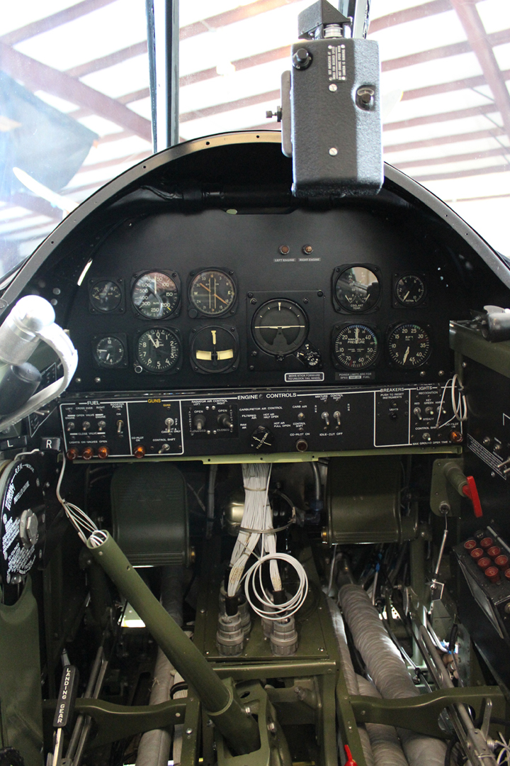
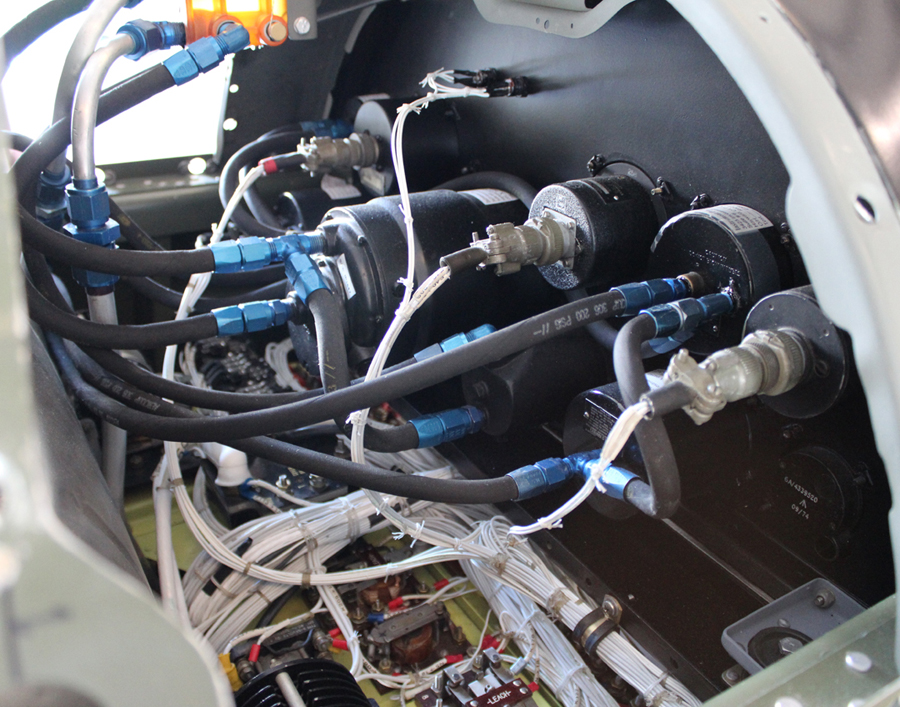
Cockpit Instrument Panels
Pilot’s instrument panel installed. The loose wires are avionics (radio) wires which still require hooking up. (photo via Tom Reilly)Hoses and wiring behind the pilot’s instrument panel. (photo via Tom Reilly)Co-pilot’s instrument panel installed. Note gun strike camera mounted. (photo via Tom Reilly)Hoses and wiring behind the co-pilot’s instrument panel. (photo via Tom Reilly)
Wingtip Lighting
Left-hand wing tip with position light installed. (photo via Tom Reilly)Right-hand wing with position and recognition lights installed. (photo via Tom Reilly)
Gear Doors – Two Main & Four Tail
A job that Tom Reilly thought would be very difficult, pressing the two inside waffle skins, turned out to be a very quick and efficient job that came out perfectly within three weeks. Two team members completed all of the interior framework, including the installation of the up-lock latch forgings (two per door) along with the two flat exterior skins.
Left-hand inboard gear door showing uplock latches, pins, hooks and the internal rib structure. (photo via Tom Reilly)Left-hand inboard gear door without external skin during final fitting. (photo via Tom Reilly)Left-hand inboard gear door with latching during final fitting. (photo via Tom Reilly)
Reilly took the two main gear doors, along with the four tail wheel doors to Kermit Weeks’ facility in Polk City, Florida for spot welding. With these six doors completed, that completes 99.9% of the sheet metal work on the XP-82. The only remaining sheet metal items are the two outboard gear doors and the adjoining lower engine close-out fairings that cannot be completed until the team ascertains the exact curvature and pattern off each outboard door. The project is waiting for these two outboard doors to be delivered.
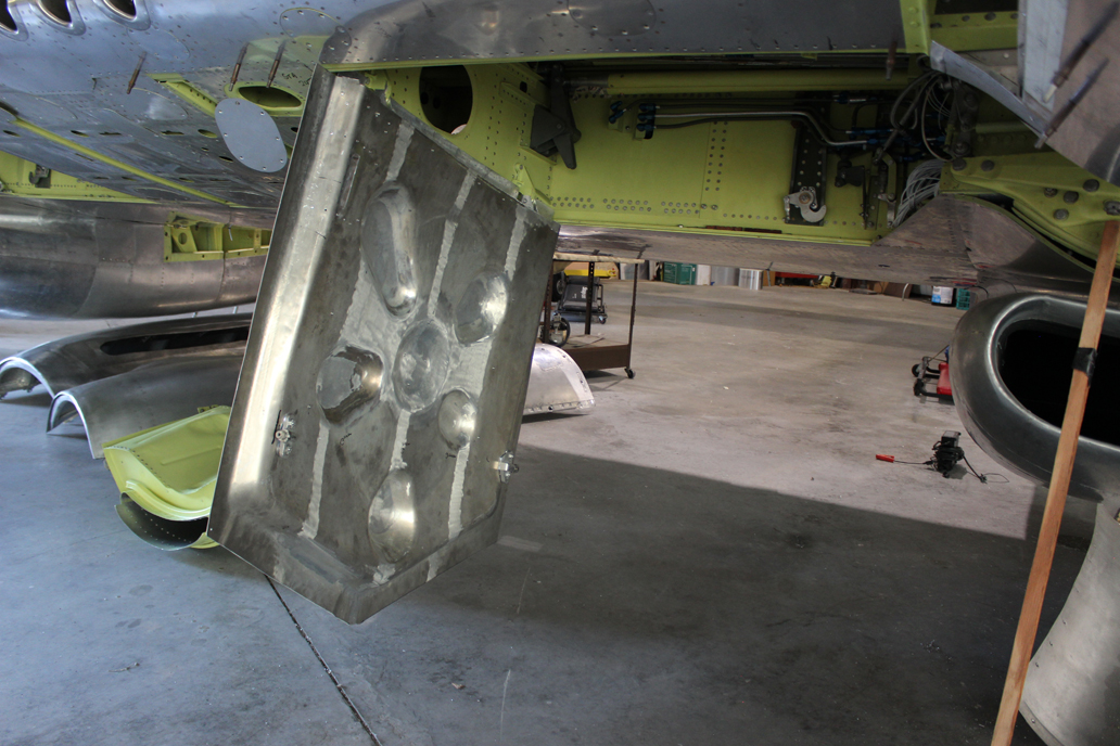
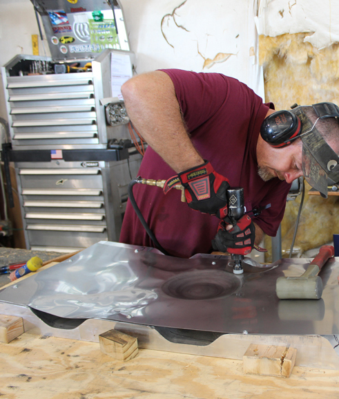
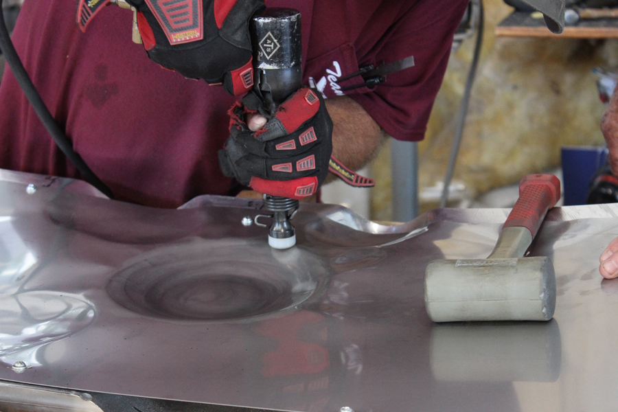
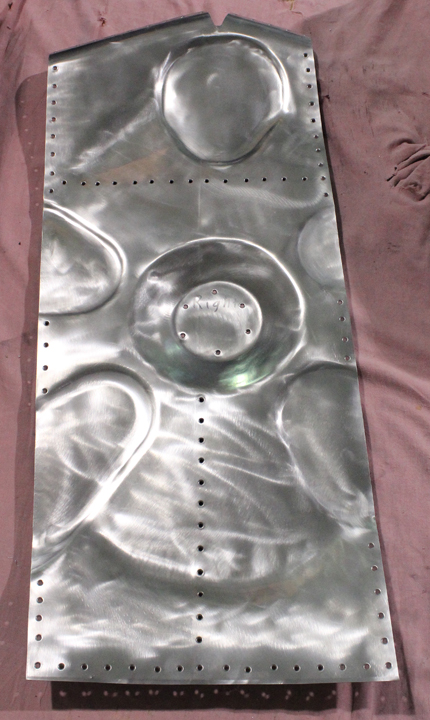
The main gear doors and interior skins went through an alodine dip (note the yellowish hue) prior to primer-painting. (photo via Tom Reilly)The exterior of one of the main gear doors with its outer skin firmly riveted in place. (photo via Tom Reilly)Shaping stainless steel sheet into the liners for the interior of the main gear doors. (photo via Tom Reilly)Larger strokes are made using the rubber mallet to ‘bash’ the sheet metal into the die form beneath, whereas finer manipulation is achieved using a rubber-tipped set on the rivet gun as shown in this closeup. (photo via Tom Reilly)The finished article, complete with rivet holes for mounting onto one of the main gear doors. (photo via Tom Reilly)
Pat Harker supplied the project with four tail gear door interior pressings. Within a few days these two team members had them fitted to the eight installed hinges with the newly formed outside skins. These outside skins are now spot welded to the inside pressings.
The tail wheel doors. (photo via Tom Reilly)
Engine Exhaust Fairings
A newly-machined press die (male) for the exhaust fairings for the right-hand engine. (photo via Tom Reilly)The female die for the engine exhaust fairing alongside the finished article. Tom and his team will use a 200 ton hydraulic press to form these .050″ stainless steel fairings between the male and female dies. (photo via Tom Reilly)
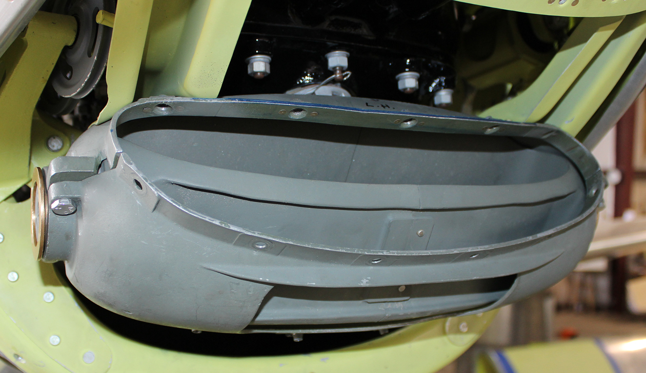
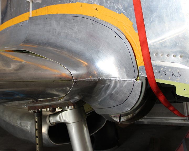
Carburetor Air Induction System
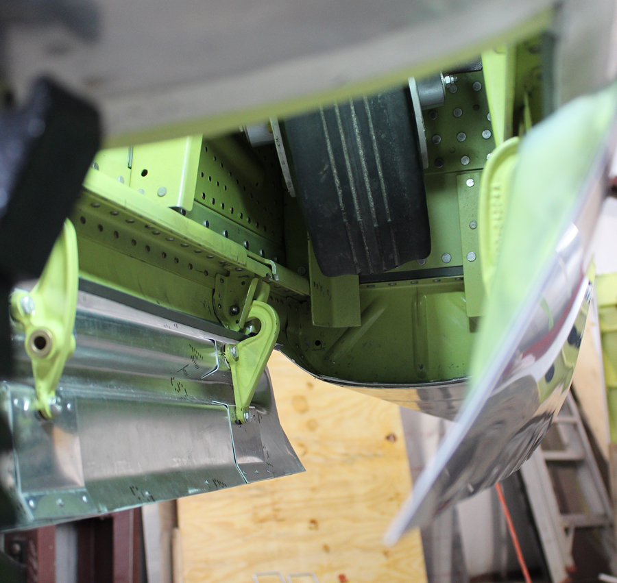
The final installation of the rotating barrels, located underneath each spinner that control the air induction temperatures, and all of the induction trunks back to the carburetor inlets are now completed. The only thing to remaining to be done on these induction systems are the rod and lever mechanism adjustments that open the hot air doors for carburetor heat.
The carburetor air intake barrel; newly completed, and installed on the right engine. (photo via Tom Reilly)A view of the newly-installed carburetor air intake barrel on the left engine giving an idea of how it operates to regulate intake air temperature. (photo via Tom Reilly)
Engine Run
In a major restoration landmark, Tom Reilly and his team pulled the XP-82 out onto the ramp, tied down both tails and chocked both main wheels and started both engines simultaneously for the first time. Reilly initially ran them at idle for about two minutes, until the oil and coolant temperatures rose, and then he brought both engines up to a little over 1000 rpm (not fast enough to check generator or propeller functions). All of the fuel, oil, tachometer and associated temperature gauges worked as expected.
Both engines running October 14th, 2017. (photo via Tom Reilly)
And that is all for this month’s report.
Many thanks again to Tom Reilly for this update. You can learn more about the project on their blog HERE. Although we are not exactly sure when the next formal update will come, please be sure to check back with WarbirdsNews in a couple of months for the next installment in the story following the XP-82′s road to recovery!
WarbirdsNews has received the latest XP-82 Twin Mustang restoration update from Tom Reilly at his workshop in Douglas, Georgia, and we thought you would all be pleased to see the latest progress!
Firewall Forwards: Two team members were able to successfully press both exhaust fairings, trim-to-fit and punch out the twelve exhaust port openings. With a small amount of final hand forming, they had them fitted, drilled and attached to both right-hand engine cowlings. They were able to use the project’s 200-ton rubber press machine to initially press the .050″-thick stainless steel and finish detail using the newly-machined, 300lb male and female press-dies.
The exhaust fairing press die. (photo via Tom Reilly)Tom Reilly preparing the female exhaust fairing press die on the fork lift prior to loading into the hydraulic rubber press. You can see the partially formed part already screwed in place. (photo via Tom Reilly)The exhaust fairing press die assembly is ready for use in this image . (photo via Tom Reilly)The male and female dies for the exhaust fairing side-by-side. It doesn’t take much imagination to realize how complex and costly these forming tools must have been to fabricate. (photo via Tom Reilly)One of the completed exhaust fairings installed on the aircraft. (photo via Tom Reilly)
Carburetor Air Temperature Hot Air Door Controls:
Mounted in the back of each induction trunk is a door that opens to control the pilot-selected amount of carburetor heat (anti-icing) into each carburetor. Either pilot can adjust the position of these doors electrically from “closed,” to “half hot” to “full hot,” depending on the outside air temperature and humidity conditions during any point in the flight.
The hookup from the electric motor that rotates the air intake barrel back to the slide mechanisms, then down through two 90-degree arms, to a cable, then through a 90-degree pulley and back to the door arm was a difficult geometry puzzle to make them work on each induction trunk.
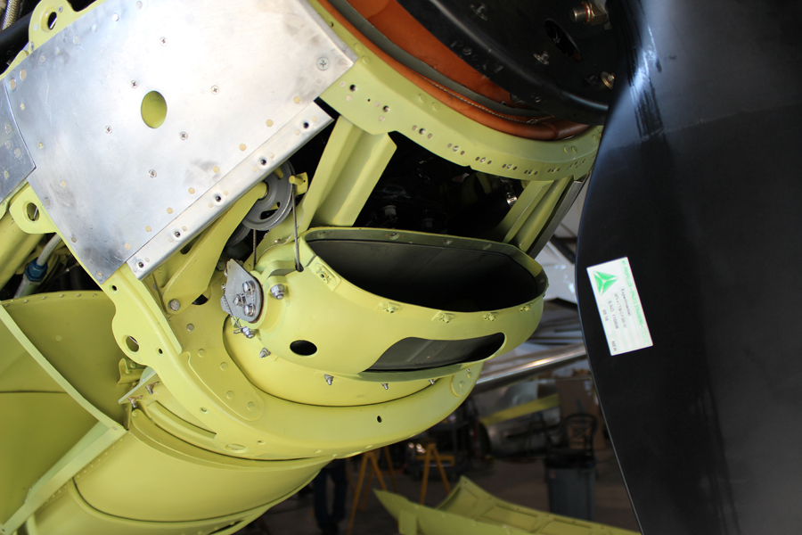
Inboard Gear Doors:
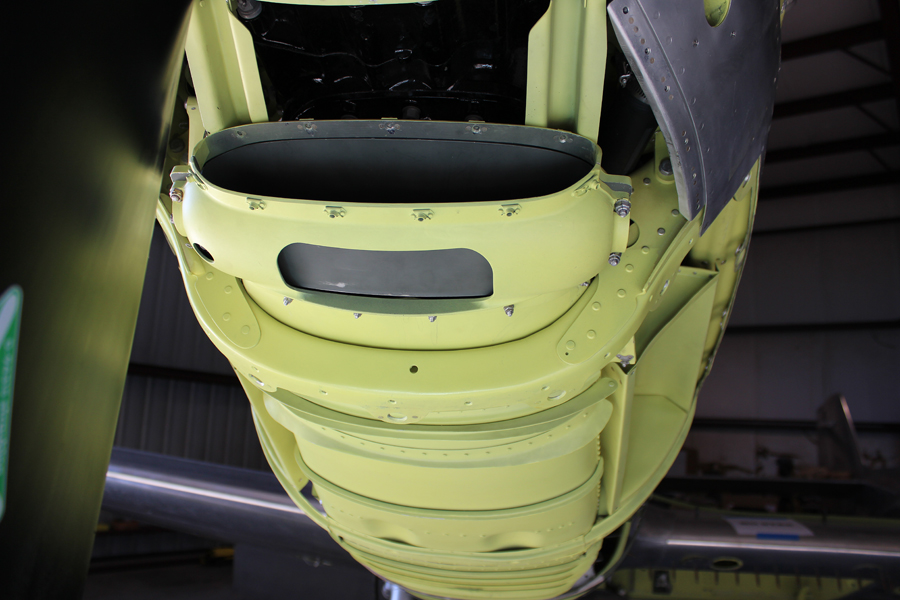
Both inboard gear doors are completely finished now, including painting the interior surfaces, and trimming. With new hinges attached, both of them are now fitted to the center section. Both doors have been hydraulically retracted, snapped into the hydraulically controlled up-lock latches and successfully released and extended numerous times.
One of the main gear doors in position on the aircraft. (photo via Tom Reilly)
Tail Gear Doors:
All four tail gear doors are now completely finished, with their interiors painted. All eight hinges and four retract rods are attached, and the assemblies final fitted into each of the two tail wheel bays. Tom Riley and the team are awaiting two small brackets that mount on the two tail wheel lower arms that the pull/push rods attach to for retraction and extension.
Freshly completed tail gear doors. (photo via Tom Reilly)The tail gear doors in position for one of the fuselages. (photo via Tom Reilly)
Aileron Bellcranks:
The team installed the aileron bellcrank boxes, one in each wing. These two boxes have a large cable sector with a lever arm that attaches to a push rod coming from the bottom of each stick. The movement of each synchronized stick (left or right) rotates the cable sector that has two cables attached to it that go out through the wing via two 90-degree pulleys and then back to another sector and arm that is attached to the ailerons.
The wing root sector box is the greyish-looking item with the bell crank poking from within it. (photo via Tom Reilly)A view of the wing root box looking down through the upper wing access panel. (photo via Tom Reilly)The aileron sector box. (photo via Tom Reilly)One of the aileron push rods which connects the stick to the wing root sector box prior to installation. (photo via Tom Reilly)
Wings/Center Section Fuel Tank Testing:
The center section has two 95-gallon fuel tanks, one located underneath each cockpit floor outboard of each gun bay. Each outboard wing holds 205 gallons of fuel and has provisions for two drop-tanks holding a total of 450 gallons under each wing. Each drop tank has the ability to be air-pressurized from the vacuum pump discharge air through a cockpit selector to air-force the fuel back to the inboard center section 95-gallon tank. Total internal fuel capacity is 600 US gallons.
In December, the team completely filled all six tanks with fuel to test for leaks.
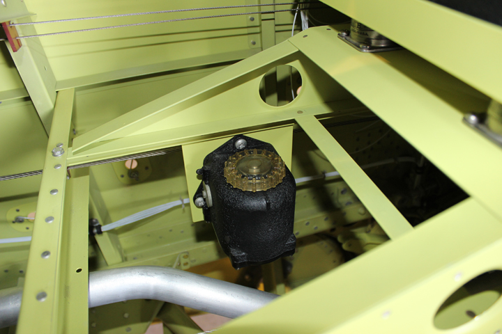
Cross-flow Check Valves:
There are two cross-flow check valves, one mounted above the belly scoop under each fuselage. These check valves control the fuel flow from the fuel tank boost pump located in each outboard wing and the fuel flow from the inboard 95-gallon tank boost pump to each engine. These valves prevent the outboard fuel being transferred to the inboard tank and vice versa. Boost pump fuel coming from either tank through the check valve housing will only go forward to the engine.
One of the cross-flow check valve drains. (photo via Tom Reilly)
Fuel Shut-off/Cross-feed Valves:
These electronic shut-off and cross-feed valves have been final-tested and had the associated hoses attached. These valves are Whittaker guillotine-style valves that have a chrome-plated sliding plate that electro-mechanically opens and closes off each port.
The fuel cross-feed valve. As you can see, the device is in the partially closed position at present. (photo via Tom Reilly)
Flaps:
The two flap hydraulic cylinders are now attached to the flap arms. The team hydraulically actuated them to test their functionality, and also adjusted the flap up-and-down stops accordingly.
The flap hydraulic cylinder attached to the flap arm in the foreground. (photo via Tom Reilly)
Flap Follow Up Mechanism:
This mechanism is mounted on the left-hand cockpit floor underneath the flap actuator handle. It is a device that synchronizes the movement of the flap handle, the flap hydraulic actuator and the position of the three flap panels.
The flap follow up mechanism. (photo via Tom Reilly)
Aileron Trim:
The team has completed, installed and tested the aileron trim bellcrank and chain/cable mechanism.
Aileron trim control mechanism. (photo via Tom Reilly)
Tail Wheel Unlocks:
The restoration team was able to manufacture the two missing tail wheel steering unlocks. These unlocks release the tail wheel steering when either stick is pushed all the way forward. They are actuated by the down-elevator cable, one in each rear fuselage.
A detail shot showing the tail wheel unlock linkages in place (note detail within black circle). (image via Tom Reilly)Another detailed image of the tailwheel unlock mechanism, this time looking from the opposite direction. (photo via Tom Reilly)
Leading Edge with Six .50 Caliber Gun Ports:
The center section leading edge has been left off in order for the restoration team to make the final adjustments on the gear door up-lock mechanisms. Now that these adjustments have been made, Tom Reilly has been final fitting the leading edge. Its installation will be completed by the end of next week.
A view of the center wing leading edge. (photo via Tom Reilly)
And that is all for this month’s report.
Many thanks again to Tom Reilly for this update. You can learn more about the project on their blog HERE. Although we are not exactly sure when the next formal update will come, please be sure to check back with WarbirdsNews in a couple of months for the next installment in the story following the XP-82′s road to recovery!
WarbirdsNews has received the latest XP-82 Twin Mustang restoration update from Tom Reilly at his workshop in Douglas, Georgia, and we thought you would all be pleased to see the latest progress!
The end of the ten-year XP-82 restoration project is in sight, and as Tom Reilly noted… the light at the end of the tunnel is not an oncoming train! The team is down to a rather short punch list with another ten weeks to go. A few of the outstanding items could have precluded the Twin Mustang prototype from making Oshkosh this year, but thankfully these potential problems have been solved.
Outdoor Gear Doors:
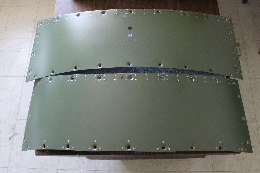
Both inboard pressings were delivered to the project about three weeks ago. Tom Reilly thought the fitting of these doors was going to be extremely difficult and time consuming, but Paul had them installed perfectly within a week. The internal framework is also now fitted and both components have been completed with the addition of the spot-welded, outside skins.
New outboard gear doors without outside skins. (photo via Tom Reilly)Gear doors with skins. (photo via Tom Reilly)
Tailwheel Doors:
The two tailwheel door retract brackets have been completed and attached. The four doors are mechanically retracted by rods attached to the tailwheel arm structure(s). The two tailwheel assemblies are not retracted by hydraulics but rather by a 3/16″ stainless steel cable running the full length of each fuselage up to a set of pulleys attached to each main landing gear retract arm. When each main gear retracts, each tailwheel is drawn up into its up-locked position along with the doors. On extension of the main gear, both tailwheel assemblies unlock, gravity-extend and cable-latch the down lock. This is a unique North American Aviation, factory-installed retract system.
A bent and corroded original part with two new ones lined up below it. (photo via Tom Reilly)Note the silver-painted item, at the top right of the image, installed in the tail, with gear doors up. (photo via Tom Reilly)Another view of the same item installed on the tail wheel mechanism, with gear doors down. (photo via Tom Reilly)
Landing Gear Retractions:
The restoration team has completed the landing gear retraction tests and timing valve adjustments that sequence the inboard gear doors opening and closing. Following both the gear-up and gear-down operations, the main inboard undercarriage doors are at rest in the closed position. Timing valves sequence the proper opening and closing of these doors for the gear to pass. It is a straight-forward NAA design that works extremely well. The following photos show how the process works, starting with retraction, and then extension. The gear starts to retract in image 1. It locks in the up position in image 3, following which the main gear door closes in images 4 – 7. Image 8 shows the beginning of the reverse process. The door starts opening, and has completed the process by image 11, when the main gear starts extending. Once the main gear is down and locked in image 13, the door begins folding back up into the closed position.
Brake Assemblies:
The last two major items that the team has been awaiting to complete the XP-82 are the brake calipers. Interestingly, this style of brake assembly was unique to the XP/F-82 Twin Mustang series, thus they were unavailable on the surplus market.
A non-airworthy and broken original brake system. (photo via Tom Reilly)Two new aluminum calipers during the process of being 3D computer milled. (photo via Tom Reilly)
The most serious of these missing brake items were the two small pressure check valve boxes. Pictures are attached. The team’s main machinist, John, expects to have both calipers completed within the next week. John was able to make a 3D print using the non-airworthy, magnesium caliper example that the team recovered from the Alaskan wreck site as a reference. He is well into completing the machining of both new aluminum calipers. BUT, the team had no samples of the small pressure check valve boxes to copy. The big problem was that the entire brake assembly was manufactured by Goodyear and the XP-82 parts books did not give any breakdown or part numbers of any of the associated Goodyear brake parts. Thus the restoration team had nothing they could take apart and copy to replace the two missing pressure check valves.
However, in a stroke of great fortune, John Soplata, the grandson of Walter and Margaret Soplata, discovered a complete XP-82 brake assembly WITH one pressure check valve. John Soplata had already come to the rescue once previously, when he discovered the elusive second main wheel in the cellar of the family home.
The entire brake and check valve assembly arrived at the XP-82’s present home in Douglas, Georgia via FED EX. Now that the team has both brake assemblies, they can salvage all of the original pistons, springs, depth indicators and slave cylinders for the project. The two original calipers are magnesium castings though, and due to corrosion issues, they could not be made airworthy. So, along with the two new calipers currently under manufacture, all that remains to complete the brake package is the duplication of the one small check valve box. This will be completed within two weeks. Not having these pressure check valves would have ground the project to a halt, and thus a time-consuming and costly bump in the road has been avoided.
The old brake set up. (photo via Tom Reilly)
Original Radios:
The restoration team was able to find the seven radios of the correct types that were originally installed in the XP-82, along with all of their associated Cannon plugs. For authenticity, Tom Reilly has duplicated the exact colors for the wires that were soldered back into the original-style plugs. To complete the original installation suite, the team still has one more Cannon plug remaining to solder, along with the antenna wires that plug into the radios and tie ups.
. (photo via Tom Reilly). (photo via Tom Reilly). (photo via Tom Reilly). (photo via Tom Reilly). (photo via Tom Reilly)
Ailerons:
All four ailerons are now permanently attached. Randall has set the balances, movement ranges, cable tensions and stops to match each cockpit stick.
One of the ailerons in place. (photo via Tom Reilly)
Rudders and Elevator:
Both rudders and the elevator are now permanently installed. Movement ranges, balances, cable tensions and control movements are now set and synchronized between each cockpit’s stick and pedals. This was quite a time consuming job getting all four pedals matched to each other and to both rudders, but now they are completely done. All safety wiring for the turnbuckles is now completed.
Leading Edge with Gun Ports:
The entire leading edge is now totally attached. This job took Paul and Randall a complete week to finish due to the final riveting and the hundreds of screws and nut plates throughout the forward spar which had to be fastened.
The leading edge gun ports. (photo via Tom Reilly)
Starrett Level:
Right forward of the left-hand tail wheel there is a 3” round hole in the left side of the fuselage that houses a mounted Starrett level that is visible to set the pitch (tail up/tail down) of the two fuselages when doing a weight and balance measurement. The 1944-dated North American Aviation XP-82 plans show a detailed picture of the level with part its number and the mounting structure. Tom Reilly instructed Weezie to contact Starrett to see if they had one of these levels in their museum that the team could acquire for installation in the XP-82 to make the restoration as original as possible. Within a few hours, she found an identical, brand new example in stock at Grainger in Orlando. What were the chances of finding a Starrett level absolutely identical to the part identified in the 74-year old parts book drawing!?
The Starrett level in place within the XP-82 airframe. (photo via Tom Reilly)The drawing associated with the aircraft level’s installation. (image via Tom Reilly)
Outboard Wings:
Both outboard wings are now totally bolted down and appropriately torqued. There were 300+ internal-wrenching bolts in all. All of the fuel feed and vent hoses are also now installed. The restoration team filled the tanks with fuel and tested all of the connections and pumps for leaks.
One of the outer wing panels. (photo via Tom Reilly)
Pitot Static Systems:
The pitot (air speed) and static (neutral air pressure) systems going to both cockpits are now completely hooked up and pre-tested for leaks. A technician from an FAA-approved repair station facility will visit the restoration shop to verify and sign off the required accuracy checks for the altimeter, transponder and encoder (tells ground controllers your altitude, air speed, etc.), pitot instrument and static air going to each air speed indicator, climb and altimeter instruments. Reilly cannot do these final checks and sign-offs himself, as an independent, FAA-licensed avionics facility must perform them.
The pitot tube. (photo via Tom Reilly)
Engine/Prop Test Runs:
Since October last year, the restoration team pulled the XP-82 outside again twice further for engine and propeller test runs. For each trial, the team would lash each tail to strong tie-down anchored rings, and add sand bags to the top of the horizontal stabilizer to prevent the tail from lifting during hard run-ups.
So far, Tom Reilly has brought the power up on each engine to 1500 rpm, about half power, and test-cycled the props. He will start the prescribed three-hour run-in schedule dictated by Vintage V12s, the company that overhauled the Twin Mustangs two Merlin engines. To date, the XP-82 has clocked 1.5 hours of ground run and system checks on each engine, with no squawks.
Test-running the engines. (photo via Tom Reilly).Test-running the engines. (photo via Tom Reilly)
Weight & Balance (W & B):
A few weeks ago, a weight and balance company from Lakeland, Florida came to perform the required W & B on the XP-82. The wood underneath the propeller hubs (in the picture) is not supporting anything; its’s just there for safety to help prevent a nose-over.
The XP-82 ready for her weight and balance operation. (photo via Tom Reilly)14,979 lbs. with 400 lbs. of sandbags on the horizontal stabilizer. (photo via Tom Reilly)
Indicators:
The restoration team was able to locate two NOS ID-42A/APS-13 radar indicators. These were installed just below the pilot and co-pilot’s cockpit glare shields. When the light comes on, it lets you know that an uninvited guest is on your tail!
Reilly’s team has been able to locate two NOS ID-42A/APS-13 radar indicators. These are installed just below the pilot and co-pilot’s glare shields. When the light comes on it lets you know that an uninvited guest is on your tail.. (photo via Tom Reilly)
Items on the “to complete” punch list:
1. After this coming week’s hard two-hour engine and propeller run-ins (no problems expected), the entire XP-82 airframe will be lightly washed down with aluminum etch and a soft Scotch Brite pad to blend out any small scratches. This will highlight the color differences between the three different aluminum alloys that had been used to skin the XP-82. If one looks closely at the original pictures of the aircraft during its first flight, these color changes are definitely noticeable.
2. The restoration team has received the stencils for all of the painted markings that are scattered over the airframe. The restoration team will apply them after the etching process.
3. The XP-82 restoration has consumed in excess of 202,000 man-hours, but is finally in the end-game. So if nothing goes ‘bump in the night’, Tom Reilly hopes to have the Twin Mustang prototype at Oshkosh this July… with time to spare.
The left-hand, right-hand and center section flaps are now permanently installed and adjusted to their four different degree stop positions. (photo via Tom Reilly)
And that is all for this month’s report.
Many thanks again to Tom Reilly for this update. You can learn more about the project on their blog HERE. Although we are not exactly sure when the next formal update will come, please be sure to check back with WarbirdsNews in a couple of months for the next installment in the story following the XP-82′s road to recovery…. who knows, the next update may include details of a first flight!
We have been following the restoration of North American XP-82 Twin Mustang 44-83887 at Tom Reilly’s workshop in Douglas, Georgia for some years now, with updates on the project coming on a near-monthly basis during this time. This past year has seen a slowdown in these reports due to the complex and unpredictable nature of every restoration as it comes close to completion. The restoration team had hoped to have the aircraft ready to fly just before EAA AirVenture Oshkosh 2018, but didn’t quite make the deadline. Now with more time to prepare for the first flight, Tom Reilly has decided to replace the original, magnesium alloy wheel rims on the aircraft with newly fabricated examples manufactured from aluminum. There are many practical reasons for this choice, and Tom Reilly explained them very well in a recent letter (see below) which we thought our readers would enjoy reading…
After much thought I have chosen a warbird restoration facility and specialty machine shop in Cameron Park, CA. Chuck Wahl, the owner, has been specializing in making replacement wheels for warbirds for a number of years. I ran my decision past John Eiler, our main machinist for your XP-82, and he agreed with my decision. Chuck has been making 32″ x 8.8″ wheels for F4U Corsairs and SBDs for a number of years.
Yesterday I sent him the lower spindle leg off of the crashed Alaska F-82 for fitting purposes, along with one of the original magnesium brake calipers. I had previously sent a non-airworthy wheel to John Eiler to copy and he is forwarding that wheel out to Chuck Wahl.
Chuck manufactures his wheels out of 7075-T6 aluminum and they have been tested to failure at over ten times the strength of the original magnesium wheel. He will be able to identically duplicate our wheel for authenticity.
The total price for these two wheels will be approximately $19K with a 3-4 week delivery period.
What were the chances of our wheels failing, probably less than zero percent. But, after two known failures of this style wheel, one on an F7F Tigercat at Oshkosh and more recently, one on a TBM Avenger, I had no choice but to make this decision.
We have had countless comments (now over 300) on our website and Facebook page, every one agreeing with my safety decision. If I were to have a wheel failure on our XP-82 the public backlash would be catastrophic; if we didn’t totally lose the airplane due to an uncontrollable magnesium fire.
Many thanks to Tom Reilly for providing these details. Like everyone, we look forwards with great anticipation to the first flight of the XP-82, and wish the entire team great success in the endeavor!
A genius is a person who displays exceptional intellectual ability or creative productivity. Tom Reilly has amply demonstrated these characteristics in the course of his decades-long career restoring vintage military aircraft, and has earned his place as a legend in the warbird community. Perhaps no project better illustrates Tom’s genius than the magnificent efforts he and his team have made in resurrecting North American XP-82 Twin Mustang 44-83887. A crowning achievement to Tom’s career, the XP-82 Twin Mustang is a remarkable specimen of aeronautical design and technology. Her restoration is a testament to the dedication and resolve Tom has demonstrated in completing this remarkable project that has spanned more than a decade from inception to completion.
The Specimen – Tom’s XP-82 Twin Mustang
The first thing that strikes anyone when approaching the XP-82 is her sheer size. She is a mammoth beast in comparison to any contemporary fighter aircraft of the day! The massive four blade propellers project skyward, and the twin fuselage structures tower above you. The wing leading edge sits at head-height, rather than meeting your shoulder. In short, the Twin Mustang is imposing, and projects her true nature as a complex, purpose-built killing machine. The center wing section houses six fifty caliber machine guns. Originally conceived to escort B-29s on extreme-range bombing missions, her 604 gallon internal fuel capacity reflects this capability. Outer wing hard points were available for drop tanks, if additional range were needed too. The Twin Mustang was fast as well, with a max true airspeed at altitude of around 440 miles per hour.
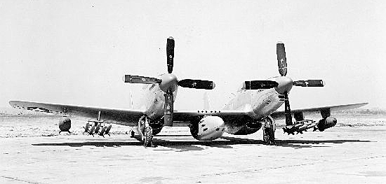
XP-82 Twin Mustang 44-83887 during her flight testing out at Muroc in 1945. Muroc is now known as Edwards Air Force Base, and home to many of the U.S. Air Force’s flight test programs. (photo via Wikipedia)
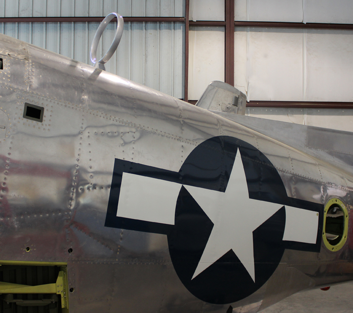
The electrical, hydraulic and fuel systems are complex in comparison to other WWII fighters, and mark a transition point in period technology. Tubing, wiring and hoses are routed throughout the wing and fuselage structure. Everything about this aircraft is robust, sturdy and purpose-built for service and combat in harsh conditions.The left and right cockpits are very similar, except for the center console on the left side. Also, the left cockpit is the only one with a gunsight, while the right side has a gun camera in its place. Switches and circuit breakers abound to the right of the pilot’s left hand seat. Because of the aircraft’s significant size, its control surfaces are commensurately large, which places a higher demand on the pilot’s strength for maneuvering than contemporary piston-powered fighters. Rudder forces, however, were light. The pilot has two throttle, mixture and propeller governor controls to the left. With its twin fuselage and tail wheel configuration and considering its massive propellers with the associated torque and P-factor they must generate on takeoff, the prospect of an engine failure at rotation is not something any pilot would relish. However, the aircraft’s engines (and propellers) rotate in opposite directions, much like those of the P-38, which helps mitigate any gyroscopic effects during normal operation.
The Quintessential XP-82 Twin Mustang
The level of detail and authenticity in Tom’s XP-82 restoration is extraordinary. Every system, component, placard, stencil, etc. that appeared on the factory-fresh aircraft back in June, 1945 appears in Tom’s restoration. Even a small factory fabrication mistake has been replicated in this aircraft; the pitot static vent was incorrectly positioned initially and then repositioned during her original manufacturing process. As a result, the restored XP-82 has preserved this tiny historical detail by replicating the holes for the incorrectly located static air port in the left fuselage and plugging them, in exactly the same way.
Mike Nixon’s Vintage V12s in Tehachapi, California overhauled the super-rare Packard-built Rolls-Royce Merlin V-1650-23 (right-turning) and -25 (left-turning) engines for the project. The carburetors, generators, and other components are all New Old Stock and/or freshly overhauled. The only significant deviation from the original design must be the propellers, of which airworthy originals were unavailable at any price. MT Propellers in Germany manufactured composite replicas for the project. The tires are new. The wheels are new. The brakes are new. A mountain of yellow tags and FAA 8130 Forms verify the pedigree of this magnificent aircraft. The radio equipment is installed, just like the radios the aircraft had when she was built. Even the shade of yellow primer paint used on the interior structures has been painstakingly researched and matched.
Origins of the XP-82 Twin Mustang and Tom’s Prototype
Tom’s XP-82 flew on April 15, 1945, the first flight for the entire breed. Following their time in flight test for the Twin Mustang program, both XP-82s (44-83887 and ‘886) served as test bed aircraft with the NACA, (precursor to NASA). Some of the testing involved equipping the aircraft with various ordinance configurations, including an eight-gun pod that hung on the center wing and fired between the propellers. A similarly positioned radar pod was also tried. Prototype Twin Mustang ‘887 flew with the NACA until July, 1950 when it was damaged in a landing accident while performing trials on an experimental ram jet.
Retrieval of the XP-82’s left hand fuselage from Soplata’s farm in 2008. (Image Credit: XP-82 Restoration Project)
Famed warbird preservationist Walter Soplata bought the damaged aircraft soon after it was written off for $300.00 without the engines or propellers. Fast-forwards to half a century later when Tom Reilly was at Soplata’s farm on December 23, 2007 and first discovered the XP-82’s left fuselage hidden under some sheet metal roofing. While Tom was in negotiations with Soplata, he quietly went about the job of finding and purchasing whatever Twin Mustang components he could find to make the project viable. After successfully concluding his purchase of the XP-82, Reilly got working on assessing what he had, what he needed, and then plotting the project out. He did have the good fortune of collaborating with the Harker brothers, who are restoring the only other civilian-owned Twin Mustang in the world, F-82E 46-0256. Ironically, this same aircraft also served with the NACA and later became part of Walt Soplata’s collection. The two teams have co-operated on a number of different aspects of their mutual restorations, including the fabrication of certain parts, such as the propellers. Since the F-82E was substantially complete, it also provided many useful reference details for the XP-82 project, although there are a lot of differences between the two variants.
The Date of the First Flight Approaches
Jewell Helton and I visited Tom and his partner Weezie Barendse on November 17, 2018. Tom was extremely generous with his time and gave us a complete tour of his facilities as well as unrestricted access to the XP-82. Reilly had hoped to have the aircraft ready to fly at EAA AirVenture Oshkosh this past summer, but the paperwork wasn’t quite signed off in time. Following the landing incident at AirVenture involving the wheel rim failure on an F7F Tigercat, Reilly decided to replace the XP-82’s original wheel rims with newly manufactured units. This has added a little extra time to the restoration, but after ten years of intense labor, the aircraft is essentially ready to go, and is expected to make her first post-restoration flight in the near future.
Alan Armstrong and Jewell Helton standing in front of the magnificent XP-82. The image further emphasizes the aircraft’s large size. (image via Alan Armstrong)
Many thanks to Alan Armstrong for his article and photographs!
The moment which every WarbirdsNews reader will have eagerly anticipated since we first started reporting on the project five years ago finally arrived with the first “official” post-restoration flight of Tom Reilly’s North American XP-82 Twin Mustang 44-83887 yesterday in Douglas, Georgia.
This of course follows the brief unplanned first flight on New Years’ Eve, 2018, the details of which are perhaps best left to Tom Reilly who described it in a phone interview with Warbird Digest’s Moreno Aguiari back in early January as follows, “The aircraft wasn’t supposed to fly that day…” In Fact the original plan was to clear the last FAA mandated high-speed taxi test, rotate for a second or two, touch back down, deploy full flaps, and brake to a stop. However, during our phone interview Reilly related that, “It accelerated so fast after the planned liftoff that test pilot Ray Fowler realized that getting it back down and stopping it in the remaining runway would be risky. So, he pushed the power back up and flew for about five minutes.” Nevertheless, the aircraft performed beautifully and “flew hands-off on the first flight with trim at almost zero degrees.”
A poor quality image, the only one available, from the unplanned first flight on New Year’s Eve 2018. (image via Tom Reilly)
As most readers will remember, yesterday’s flight had originally been mooted for July last year, but the team were not quite able to get the final paperwork signatures sorted in time to fly before EAA Oshkosh AirVenture2018. As it happened, an incident at Oshkosh involving a wheel failure on a Grumman F7F Tigercat prompted Reilly to further delay the first flight in order to have some brand new wheel rims manufactured rather than risk the XP-82 on her original magnesium-alloy castings. Chuck Wahl’s Vulture’s Row Aviation machined Reilly a replacement set of wheel rims from billet aluminum which, while adding $36,000 to the restoration cost, will provide extra peace-of-mind that a newly-made part usually offers.
Ray Fowler making his final adjustments before starting up the Twin Mustang’s unique set of counter-rotating Merlin engines.
Experienced warbird pilot Ray Fowler was at the controls again yesterday as the dual seat, dual fuselage fighter roared down the runway, its two Merlin engines powering counter-rotating propellers which beat the air in the quest for flight. Lift off was smooth as this unique aircraft took to the skies. A small crowd gathered to witness this historic event, chief among them Tom Reilly and his restoration crew who had performed a minor miracle in resurrecting this long-forgotten warbird which sat for decades as a collection of parts on Walt Soplata’s farm in Newbury, Ohio. Great credit must be shown to Soplata and his family for preserving the aircraft, not to mention Tom Reilly and his investors for having the vision – and the fortitude – to restore this magnificent aircraft back to where she belongs.
Ray Fowler lifting off in the XP-82 Twin Mustang during the first “official” post-restoration flight in Douglas, Georgia. (image capture from video)
In a recent phone interview, Tom Reilly told your editor that following the aircraft’s return to flight, Ray Fowler will fly off fifteen hours in the XP-82 to both satisfy the FAA requirements for the airframe’s airworthiness and also for the pilot to qualify for his Twin Mustang type rating. Fowler will become the world’s only currently certified Twin Mustang pilot as a result.
Ray Fowler taxiing home after the first official flight in the XP-82. (video screen capture)
When asked whether he will fly the aircraft himself, Reilly stated that he’s not sure whether he will or not. “I’m a bomber guy, not a fighter guy,” he stated. If he does fly the Twin Mustang, it will only be from the right seat. “It’s been a very fun job,” Reilly continues, ” a team effort, not a Tom Reilly effort.” So after more than ten years, and 207,000 “man and woman hours” as Reilly mentioned, the world finally has a Twin Mustang flying again, and long may it continue to be so. Reilly wouldn’t say exactly what the aircraft’s future will hold, noting it isn’t for sale, although there’s always a “right price” should one be offered.
Click HERE to read our previous articles about this amazing restoration. Check out below the video montage from iPhone clips.
Many thanks to those who supplied us with the images and video clips in this piece.